

2.5 Basics of Component Modeling in WSM
69
the model, each of its components is declared, and each connection between the two
components is represented by a linking equation, which are listed in the equation
section.
However, it is more convenient to do this in graphical mode, switching to the
mode of viewing component properties.
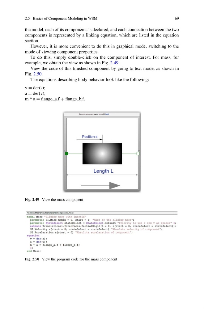
To do this, simply double-click on the component of interest. For mass, for
example, we obtain the view as shown in Fig. 2.49.
View the code of this finished component by going to text mode, as shown in
Fig. 2.50.
The equations describing body behavior look like the following:
v = der(s);
a = der(v);
m * a = flange_a.f + flange_b.f.
Fig. 2.49 View the mass component
Fig. 2.50 View the program code for the mass component
69
the model, each of its components is declared, and each connection between the two
components is represented by a linking equation, which are listed in the equation
section.
However, it is more convenient to do this in graphical mode, switching to the
mode of viewing component properties.
To do this, simply double-click on the component of interest. For mass, for
example, we obtain the view as shown in Fig. 2.49.
View the code of this finished component by going to text mode, as shown in
Fig. 2.50.
The equations describing body behavior look like the following:
v = der(s);
a = der(v);
m * a = flange_a.f + flange_b.f.
Fig. 2.49 View the mass component
Fig. 2.50 View the program code for the mass component