

2.4 Creating a Dynamic Model in Wolfram SystemModeler
57
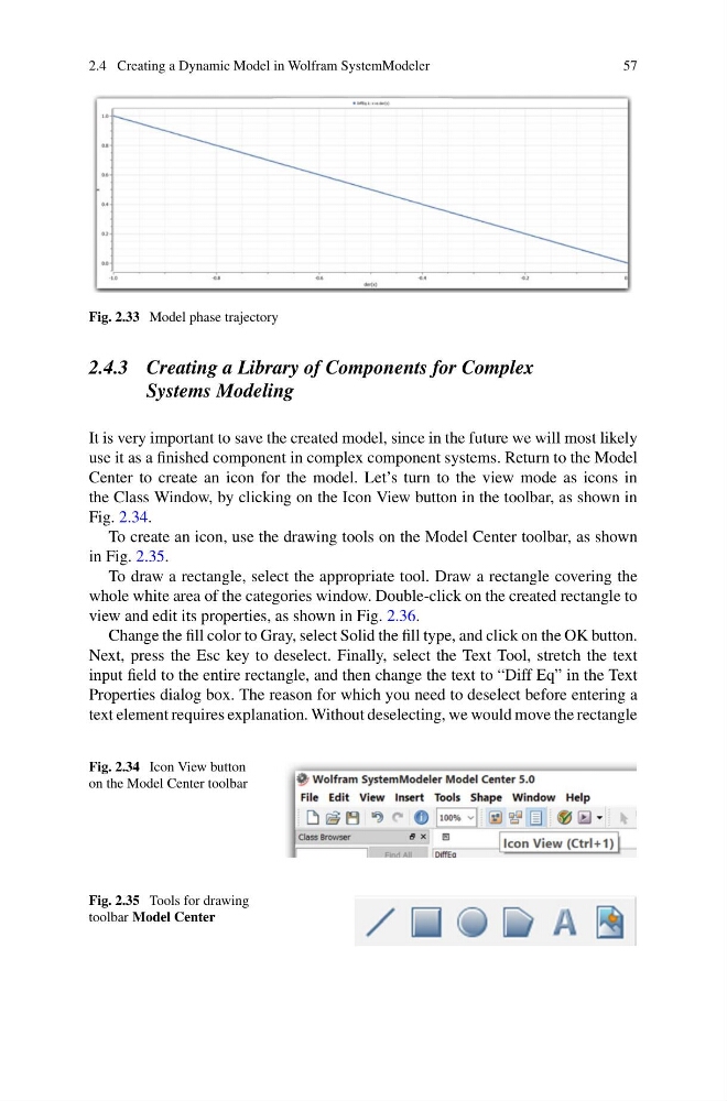
Fig. 2.33 Model phase trajectory
2.4.3 Creating a Library of Components for Complex
Systems Modeling
It is very important to save the created model, since in the future we will most likely
use it as a finished component in complex component systems. Return to the Model
Center to create an icon for the model. Let’s turn to the view mode as icons in
the Class Window, by clicking on the Icon View button in the toolbar, as shown in
Fig. 2.34.
To create an icon, use the drawing tools on the Model Center toolbar, as shown
in Fig. 2.35.
To draw a rectangle, select the appropriate tool. Draw a rectangle covering the
whole white area of the categories window. Double-click on the created rectangle to
view and edit its properties, as shown in Fig. 2.36.
Change the fill color to Gray, select Solid the fill type, and click on the OK button.
Next, press the Esc key to deselect. Finally, select the Text Tool, stretch the text
input field to the entire rectangle, and then change the text to “Diff Eq” in the Text
Properties dialog box. The reason for which you need to deselect before entering a
text element requires explanation. Without deselecting, we would move the rectangle
Fig. 2.34 Icon View button
on the Model Center toolbar
Fig. 2.35 Tools for drawing
toolbar Model Center
57
Fig. 2.33 Model phase trajectory
2.4.3 Creating a Library of Components for Complex
Systems Modeling
It is very important to save the created model, since in the future we will most likely
use it as a finished component in complex component systems. Return to the Model
Center to create an icon for the model. Let’s turn to the view mode as icons in
the Class Window, by clicking on the Icon View button in the toolbar, as shown in
Fig. 2.34.
To create an icon, use the drawing tools on the Model Center toolbar, as shown
in Fig. 2.35.
To draw a rectangle, select the appropriate tool. Draw a rectangle covering the
whole white area of the categories window. Double-click on the created rectangle to
view and edit its properties, as shown in Fig. 2.36.
Change the fill color to Gray, select Solid the fill type, and click on the OK button.
Next, press the Esc key to deselect. Finally, select the Text Tool, stretch the text
input field to the entire rectangle, and then change the text to “Diff Eq” in the Text
Properties dialog box. The reason for which you need to deselect before entering a
text element requires explanation. Without deselecting, we would move the rectangle
Fig. 2.34 Icon View button
on the Model Center toolbar
Fig. 2.35 Tools for drawing
toolbar Model Center