

46
2 Description of the Wolfram SystemModeler
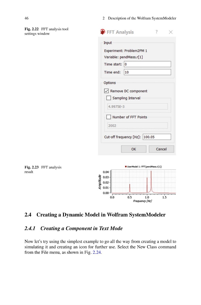
Fig. 2.22 FFT analysis tool
settings window
Fig. 2.23 FFT analysis
result
2.4 Creating a Dynamic Model in Wolfram SystemModeler
2.4.1 Creating a Component in Text Mode
Now let’s try using the simplest example to go all the way from creating a model to
simulating it and creating an icon for further use. Select the New Class command
from the File menu, as shown in Fig. 2.24.
2 Description of the Wolfram SystemModeler
Fig. 2.22 FFT analysis tool
settings window
Fig. 2.23 FFT analysis
result
2.4 Creating a Dynamic Model in Wolfram SystemModeler
2.4.1 Creating a Component in Text Mode
Now let’s try using the simplest example to go all the way from creating a model to
simulating it and creating an icon for further use. Select the New Class command
from the File menu, as shown in Fig. 2.24.