

6.3 Inverted Pendulum Problem
257
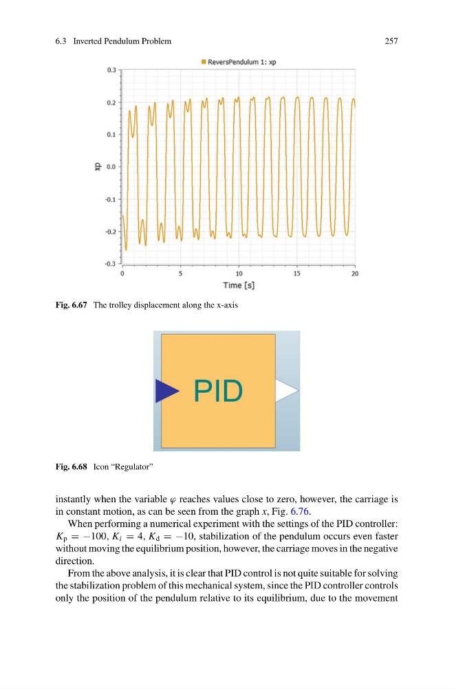
Fig. 6.67 The trolley displacement along the x-axis
Fig. 6.68 Icon “Regulator”
instantly when the variable ϕ reaches values close to zero, however, the carriage is
in constant motion, as can be seen from the graph x, Fig. 6.76.
When performing a numerical experiment with the settings of the PID controller:
K p = −100, K i = 4, K d = −10, stabilization of the pendulum occurs even faster
without moving the equilibrium position, however, the carriage moves in the negative
direction.
From the above analysis, it is clear that PID control is not quite suitable for solving
the stabilization problem of this mechanical system, since the PID controller controls
only the position of the pendulum relative to its equilibrium, due to the movement
257
Fig. 6.67 The trolley displacement along the x-axis
Fig. 6.68 Icon “Regulator”
instantly when the variable ϕ reaches values close to zero, however, the carriage is
in constant motion, as can be seen from the graph x, Fig. 6.76.
When performing a numerical experiment with the settings of the PID controller:
K p = −100, K i = 4, K d = −10, stabilization of the pendulum occurs even faster
without moving the equilibrium position, however, the carriage moves in the negative
direction.
From the above analysis, it is clear that PID control is not quite suitable for solving
the stabilization problem of this mechanical system, since the PID controller controls
only the position of the pendulum relative to its equilibrium, due to the movement