

232
6 Hierarchical Component Models
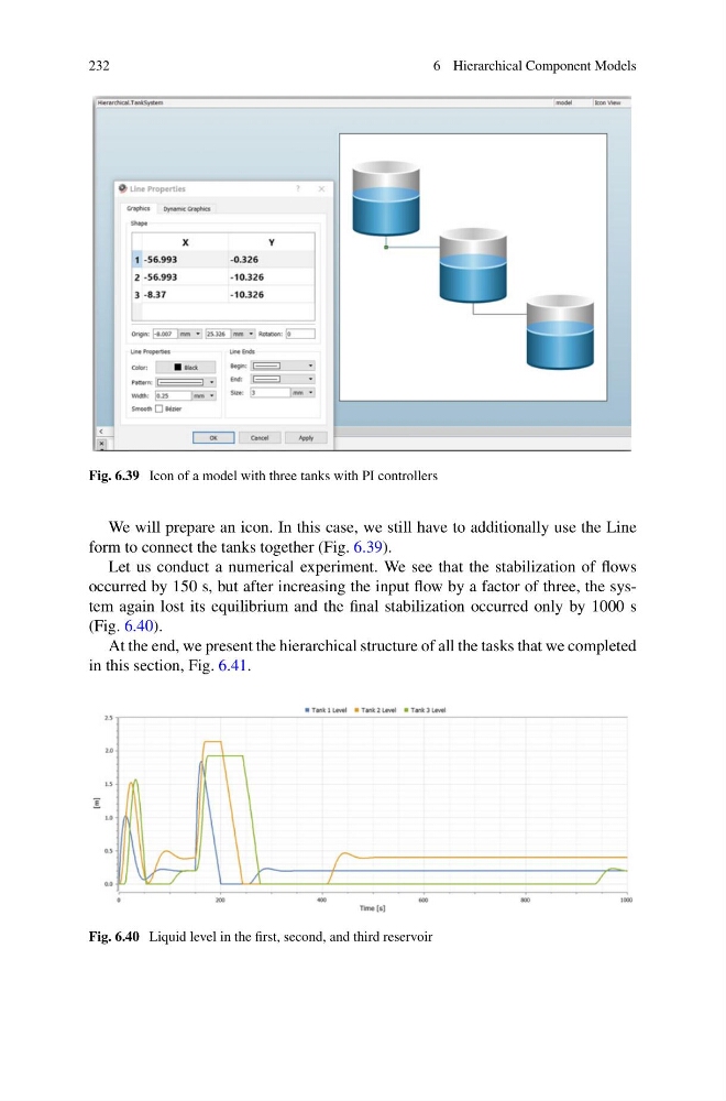
Fig. 6.39 Icon of a model with three tanks with PI controllers
We will prepare an icon. In this case, we still have to additionally use the Line
form to connect the tanks together (Fig. 6.39).
Let us conduct a numerical experiment. We see that the stabilization of flows
occurred by 150 s, but after increasing the input flow by a factor of three, the system again lost its equilibrium and the final stabilization occurred only by 1000 s
(Fig. 6.40).
At the end, we present the hierarchical structure of all the tasks that we completed
in this section, Fig. 6.41.
Fig. 6.40 Liquid level in the first, second, and third reservoir
6 Hierarchical Component Models
Fig. 6.39 Icon of a model with three tanks with PI controllers
We will prepare an icon. In this case, we still have to additionally use the Line
form to connect the tanks together (Fig. 6.39).
Let us conduct a numerical experiment. We see that the stabilization of flows
occurred by 150 s, but after increasing the input flow by a factor of three, the system again lost its equilibrium and the final stabilization occurred only by 1000 s
(Fig. 6.40).
At the end, we present the hierarchical structure of all the tasks that we completed
in this section, Fig. 6.41.
Fig. 6.40 Liquid level in the first, second, and third reservoir