

6.1 Draining of a Tank
229
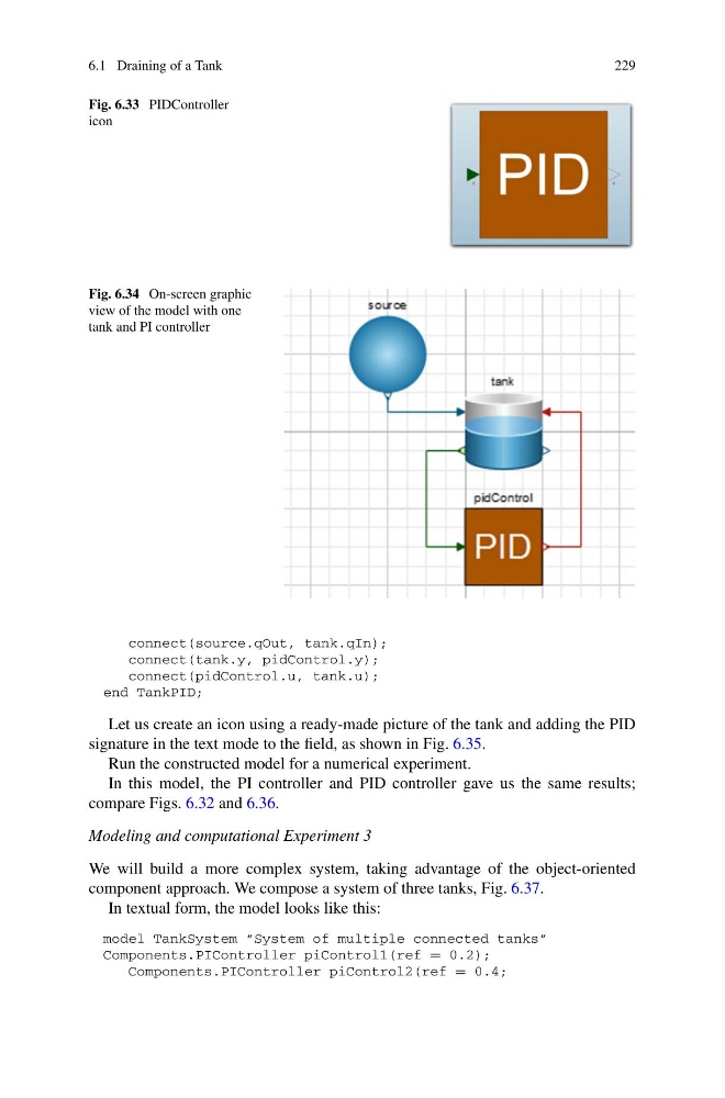
Fig. 6.33 PIDController
icon
Fig. 6.34 On-screen graphic
view of the model with one
tank and PI controller
connect(source.qOut, tank.qIn);
connect(tank.y, pidControl.y);
connect(pidControl.u, tank.u);
end TankPID;
Let us create an icon using a ready-made picture of the tank and adding the PID
signature in the text mode to the field, as shown in Fig. 6.35.
Run the constructed model for a numerical experiment.
In this model, the PI controller and PID controller gave us the same results;
compare Figs. 6.32 and 6.36.
Modeling and computational Experiment 3
We will build a more complex system, taking advantage of the object-oriented
component approach. We compose a system of three tanks, Fig. 6.37.
In textual form, the model looks like this:
model TankSystem ”System of multiple connected tanks”
Components.PIController piControl1(ref = 0.2);
Components.PIController piControl2(ref = 0.4;
229
Fig. 6.33 PIDController
icon
Fig. 6.34 On-screen graphic
view of the model with one
tank and PI controller
connect(source.qOut, tank.qIn);
connect(tank.y, pidControl.y);
connect(pidControl.u, tank.u);
end TankPID;
Let us create an icon using a ready-made picture of the tank and adding the PID
signature in the text mode to the field, as shown in Fig. 6.35.
Run the constructed model for a numerical experiment.
In this model, the PI controller and PID controller gave us the same results;
compare Figs. 6.32 and 6.36.
Modeling and computational Experiment 3
We will build a more complex system, taking advantage of the object-oriented
component approach. We compose a system of three tanks, Fig. 6.37.
In textual form, the model looks like this:
model TankSystem ”System of multiple connected tanks”
Components.PIController piControl1(ref = 0.2);
Components.PIController piControl2(ref = 0.4;