

218
6 Hierarchical Component Models
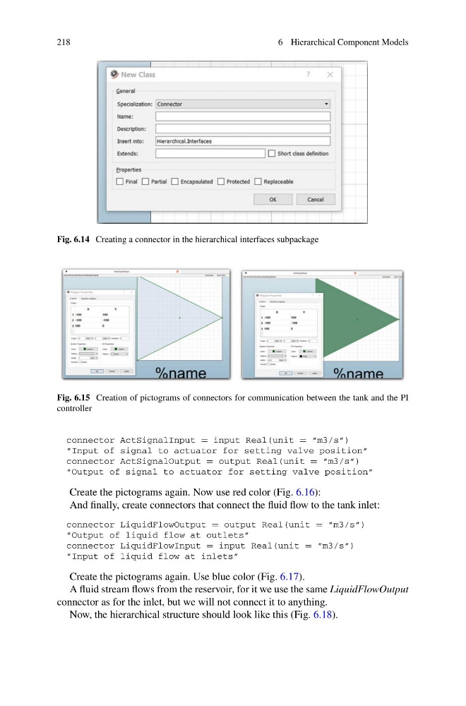
Fig. 6.14 Creating a connector in the hierarchical interfaces subpackage
Fig. 6.15 Creation of pictograms of connectors for communication between the tank and the PI
controller
connector ActSignalInput = input Real(unit = ”m3/s”)
”Input of signal to actuator for setting valve position”
connector ActSignalOutput = output Real(unit = ”m3/s”)
”Output of signal to actuator for setting valve position”
Create the pictograms again. Now use red color (Fig. 6.16):
And finally, create connectors that connect the fluid flow to the tank inlet:
connector LiquidFlowOutput = output Real(unit = ”m3/s”)
”Output of liquid flow at outlets”
connector LiquidFlowInput = input Real(unit = ”m3/s”)
”Input of liquid flow at inlets”
Create the pictograms again. Use blue color (Fig. 6.17).
A fluid stream flows from the reservoir, for it we use the same LiquidFlowOutput
connector as for the inlet, but we will not connect it to anything.
Now, the hierarchical structure should look like this (Fig. 6.18).
6 Hierarchical Component Models
Fig. 6.14 Creating a connector in the hierarchical interfaces subpackage
Fig. 6.15 Creation of pictograms of connectors for communication between the tank and the PI
controller
connector ActSignalInput = input Real(unit = ”m3/s”)
”Input of signal to actuator for setting valve position”
connector ActSignalOutput = output Real(unit = ”m3/s”)
”Output of signal to actuator for setting valve position”
Create the pictograms again. Now use red color (Fig. 6.16):
And finally, create connectors that connect the fluid flow to the tank inlet:
connector LiquidFlowOutput = output Real(unit = ”m3/s”)
”Output of liquid flow at outlets”
connector LiquidFlowInput = input Real(unit = ”m3/s”)
”Input of liquid flow at inlets”
Create the pictograms again. Use blue color (Fig. 6.17).
A fluid stream flows from the reservoir, for it we use the same LiquidFlowOutput
connector as for the inlet, but we will not connect it to anything.
Now, the hierarchical structure should look like this (Fig. 6.18).