

208
6 Hierarchical Component Models
The presence of a connection between contacts means that the values of the
variables corresponding to the contacts are equal at any time. In modern visual
packages, there are two kinds of connections:
(1) Unidirectional (oriented), and then, the connected contacts are divided into a
receiver and a source, and it is also postulated that the receiver cannot influence
the source.
The oriented block is used for the design of input-state-output systems. The use
of oriented blocks involves the introduction of restrictions on the use of phase vector
variables in the preparation of equations describing the behavior.
(2) Bidirectional (non-oriented), in this case, the connected contacts are equal. The
idea to use non-oriented blocks as components arose a very long time ago and
is especially vivid in the design of electrical circuits.
The development of this approach is the connection through the contacts of blocks
containing a description of behavior in the form of systems of algebraic and differential equations. The main idea of the approach is very well expressed in the definition
of “language for modeling physical systems.” When using the traditional block modeling approach to describe a number of real systems, serious restrictions arise on the
type of blocks.
This chapter is devoted to building hierarchical models and creating your own
libraries in the SystemModeler package. First, a model of a tank with a flat bottom
is developed, then a similar model based on components is created. We will also be
able to appreciate the flexibility of this approach, allowing us to test new scenarios.
6.1 Draining of a Tank
Formulation of Problem 1
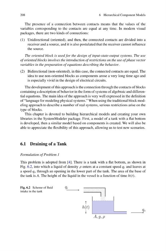
This problem is adopted from [4]. There is a tank with a flat bottom, as shown in
Fig. 6.2, into which a liquid of density ρ enters at a constant speed q i and leaves at
a speed q o through an opening in the lower part of the tank. The area of the base of
the tank is A. The height of the liquid in the vessel is a function of time h(t).
Fig. 6.2 Scheme of fluid
intake in the tank
6 Hierarchical Component Models
The presence of a connection between contacts means that the values of the
variables corresponding to the contacts are equal at any time. In modern visual
packages, there are two kinds of connections:
(1) Unidirectional (oriented), and then, the connected contacts are divided into a
receiver and a source, and it is also postulated that the receiver cannot influence
the source.
The oriented block is used for the design of input-state-output systems. The use
of oriented blocks involves the introduction of restrictions on the use of phase vector
variables in the preparation of equations describing the behavior.
(2) Bidirectional (non-oriented), in this case, the connected contacts are equal. The
idea to use non-oriented blocks as components arose a very long time ago and
is especially vivid in the design of electrical circuits.
The development of this approach is the connection through the contacts of blocks
containing a description of behavior in the form of systems of algebraic and differential equations. The main idea of the approach is very well expressed in the definition
of “language for modeling physical systems.” When using the traditional block modeling approach to describe a number of real systems, serious restrictions arise on the
type of blocks.
This chapter is devoted to building hierarchical models and creating your own
libraries in the SystemModeler package. First, a model of a tank with a flat bottom
is developed, then a similar model based on components is created. We will also be
able to appreciate the flexibility of this approach, allowing us to test new scenarios.
6.1 Draining of a Tank
Formulation of Problem 1
This problem is adopted from [4]. There is a tank with a flat bottom, as shown in
Fig. 6.2, into which a liquid of density ρ enters at a constant speed q i and leaves at
a speed q o through an opening in the lower part of the tank. The area of the base of
the tank is A. The height of the liquid in the vessel is a function of time h(t).
Fig. 6.2 Scheme of fluid
intake in the tank