

Chapter 6
Hierarchical Component Models
The basis of any modeling system is a block, an analog of a real device or a component.
Blocks can be interconnected, forming functional diagrams located on the plane. Any
functional diagram can be considered as a complex unit. These complex blocks with
internal structure we can again interconnect building hierarchical multi-level systems
[1–3].
A block is an independent element that functions according to its internal laws and
interacts with the outside world (other blocks) through a given set of variables called
interface variables. A block is usually drawn in the form of a rectangle, depicting
interface variables of various types next to it, for example, these variables can be
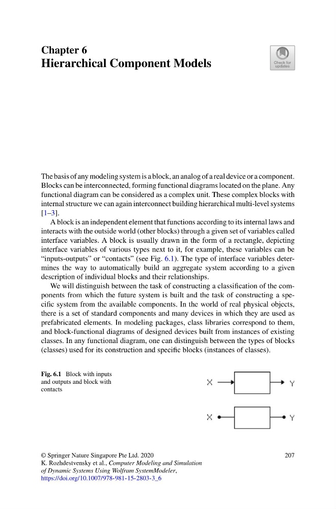
“inputs-outputs” or “contacts” (see Fig. 6.1). The type of interface variables determines the way to automatically build an aggregate system according to a given
description of individual blocks and their relationships.
We will distinguish between the task of constructing a classification of the components from which the future system is built and the task of constructing a specific system from the available components. In the world of real physical objects,
there is a set of standard components and many devices in which they are used as
prefabricated elements. In modeling packages, class libraries correspond to them,
and block-functional diagrams of designed devices built from instances of existing
classes. In any functional diagram, one can distinguish between the types of blocks
(classes) used for its construction and specific blocks (instances of classes).
Fig. 6.1 Block with inputs
and outputs and block with
contacts
© Springer Nature Singapore Pte Ltd. 2020
K. Rozhdestvensky et al., Computer Modeling and Simulation
of Dynamic Systems Using Wolfram SystemModeler,
https://doi.org/10.1007/978-981-15-2803-3_6
207
Hierarchical Component Models
The basis of any modeling system is a block, an analog of a real device or a component.
Blocks can be interconnected, forming functional diagrams located on the plane. Any
functional diagram can be considered as a complex unit. These complex blocks with
internal structure we can again interconnect building hierarchical multi-level systems
[1–3].
A block is an independent element that functions according to its internal laws and
interacts with the outside world (other blocks) through a given set of variables called
interface variables. A block is usually drawn in the form of a rectangle, depicting
interface variables of various types next to it, for example, these variables can be
“inputs-outputs” or “contacts” (see Fig. 6.1). The type of interface variables determines the way to automatically build an aggregate system according to a given
description of individual blocks and their relationships.
We will distinguish between the task of constructing a classification of the components from which the future system is built and the task of constructing a specific system from the available components. In the world of real physical objects,
there is a set of standard components and many devices in which they are used as
prefabricated elements. In modeling packages, class libraries correspond to them,
and block-functional diagrams of designed devices built from instances of existing
classes. In any functional diagram, one can distinguish between the types of blocks
(classes) used for its construction and specific blocks (instances of classes).
Fig. 6.1 Block with inputs
and outputs and block with
contacts
© Springer Nature Singapore Pte Ltd. 2020
K. Rozhdestvensky et al., Computer Modeling and Simulation
of Dynamic Systems Using Wolfram SystemModeler,
https://doi.org/10.1007/978-981-15-2803-3_6
207