

202
5 Modeling of Mechanical Oscillatory Systems …
order to achieve the fulfillment of the set initial conditions. As a result, the amplitude
of the oscillations decreased (blue and yellow graphs).
The stiffness found as a result of the computational experiment turned out to be
k 1 = 17.1675 N/m and k 2 = 34.335 N/m.
5.9 Sophisticated Mechanical System with Springs
and Block
Formulation of the problem
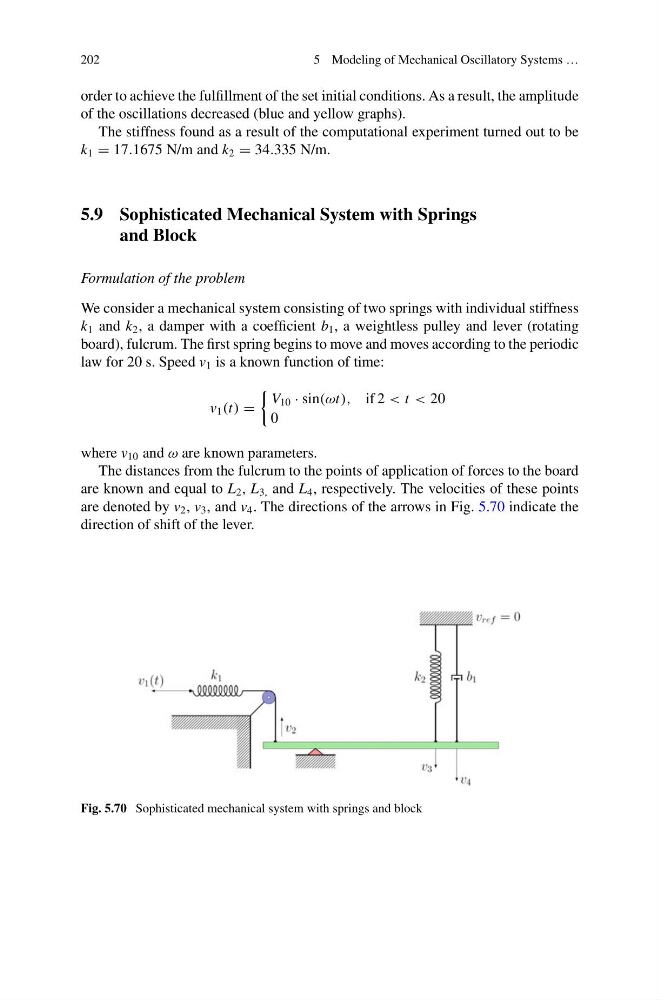
We consider a mechanical system consisting of two springs with individual stiffness
k 1 and k 2 , a damper with a coefficient b 1 , a weightless pulley and lever (rotating
board), fulcrum. The first spring begins to move and moves according to the periodic
law for 20 s. Speed v 1 is a known function of time:
v 1 (t) =
V 10 · sin(ωt), if 2 < t < 20
0
where v 10 and ω are known parameters.
The distances from the fulcrum to the points of application of forces to the board
are known and equal to L 2 , L 3, and L 4 , respectively. The velocities of these points
are denoted by v 2 , v 3 , and v 4 . The directions of the arrows in Fig. 5.70 indicate the
direction of shift of the lever.
Fig. 5.70 Sophisticated mechanical system with springs and block
5 Modeling of Mechanical Oscillatory Systems …
order to achieve the fulfillment of the set initial conditions. As a result, the amplitude
of the oscillations decreased (blue and yellow graphs).
The stiffness found as a result of the computational experiment turned out to be
k 1 = 17.1675 N/m and k 2 = 34.335 N/m.
5.9 Sophisticated Mechanical System with Springs
and Block
Formulation of the problem
We consider a mechanical system consisting of two springs with individual stiffness
k 1 and k 2 , a damper with a coefficient b 1 , a weightless pulley and lever (rotating
board), fulcrum. The first spring begins to move and moves according to the periodic
law for 20 s. Speed v 1 is a known function of time:
v 1 (t) =
V 10 · sin(ωt), if 2 < t < 20
0
where v 10 and ω are known parameters.
The distances from the fulcrum to the points of application of forces to the board
are known and equal to L 2 , L 3, and L 4 , respectively. The velocities of these points
are denoted by v 2 , v 3 , and v 4 . The directions of the arrows in Fig. 5.70 indicate the
direction of shift of the lever.
Fig. 5.70 Sophisticated mechanical system with springs and block