

5.8 Mechanical System with Two Springs and a Block
201
// For block and load:
ML = if time < 5 then ML0 else 0;
(Mp + ML)*der(v3) = F1 + F2 - g*(Mp + ML);
v1 = v3 - Rp*w;
v2 = v3 + Rp*w;
J*der(w) = Rp*(F2 - F1);
// Initial equations
initial equation
der(e1) = 0;
der(e2) = 0;
der(v3) = 0;
der(w) = 0;
e1 = 3;
e2 = 1.5;
annotation(experiment(StartTime=0,StopTime=25));
//Specify the simulation time
end SpringPulleyLoad3;
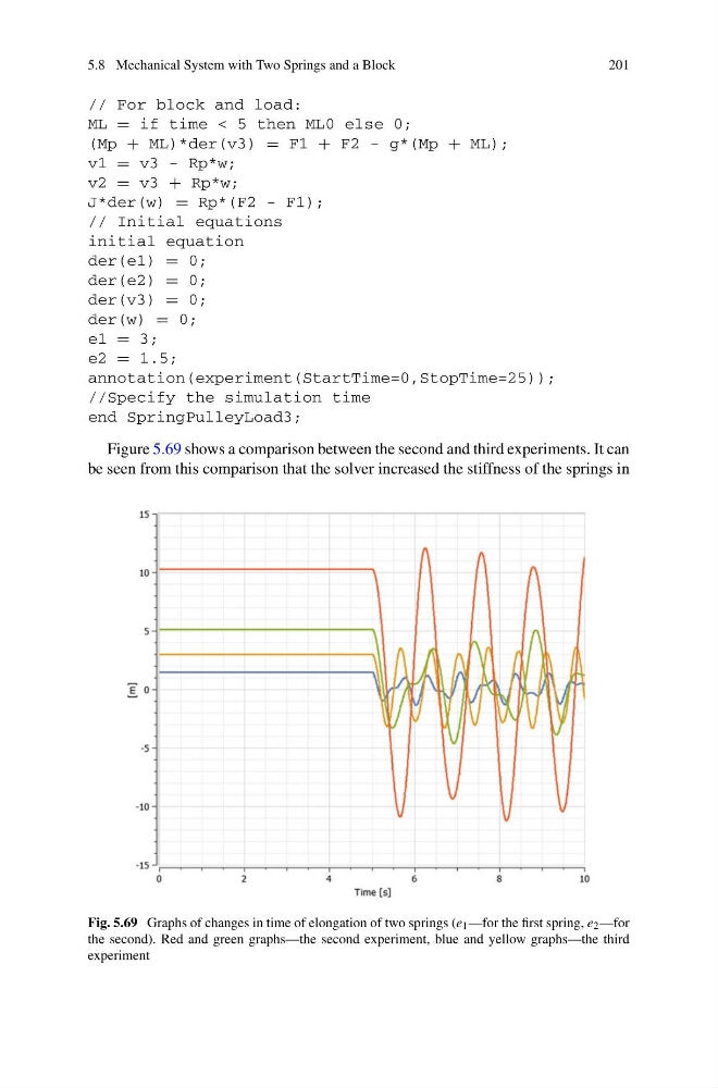
Figure 5.69 shows a comparison between the second and third experiments. It can
be seen from this comparison that the solver increased the stiffness of the springs in
Fig. 5.69 Graphs of changes in time of elongation of two springs (e 1 —for the first spring, e 2 —for
the second). Red and green graphs—the second experiment, blue and yellow graphs—the third
experiment
201
// For block and load:
ML = if time < 5 then ML0 else 0;
(Mp + ML)*der(v3) = F1 + F2 - g*(Mp + ML);
v1 = v3 - Rp*w;
v2 = v3 + Rp*w;
J*der(w) = Rp*(F2 - F1);
// Initial equations
initial equation
der(e1) = 0;
der(e2) = 0;
der(v3) = 0;
der(w) = 0;
e1 = 3;
e2 = 1.5;
annotation(experiment(StartTime=0,StopTime=25));
//Specify the simulation time
end SpringPulleyLoad3;
Figure 5.69 shows a comparison between the second and third experiments. It can
be seen from this comparison that the solver increased the stiffness of the springs in
Fig. 5.69 Graphs of changes in time of elongation of two springs (e 1 —for the first spring, e 2 —for
the second). Red and green graphs—the second experiment, blue and yellow graphs—the third
experiment