

5.7 Gear Rotary Mechanical System
185
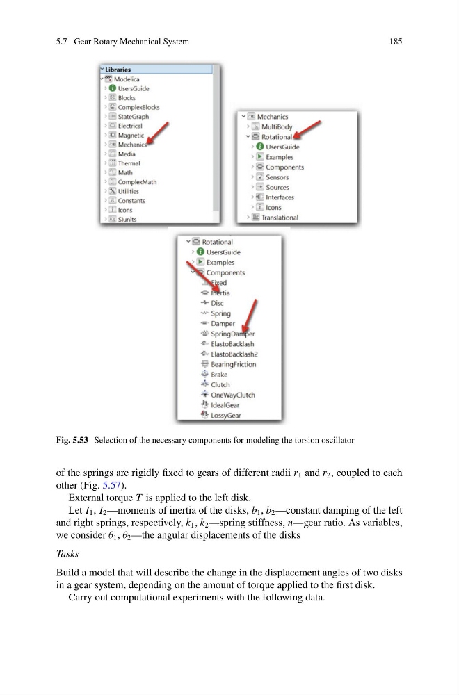
Fig. 5.53 Selection of the necessary components for modeling the torsion oscillator
of the springs are rigidly fixed to gears of different radii r 1 and r 2 , coupled to each
other (Fig. 5.57).
External torque T is applied to the left disk.
Let I 1 , I 2 —moments of inertia of the disks, b 1 , b 2 —constant damping of the left
and right springs, respectively, k 1 , k 2 —spring stiffness, n—gear ratio. As variables,
we consider θ 1 , θ 2 —the angular displacements of the disks
Tasks
Build a model that will describe the change in the displacement angles of two disks
in a gear system, depending on the amount of torque applied to the first disk.
Carry out computational experiments with the following data.
185
Fig. 5.53 Selection of the necessary components for modeling the torsion oscillator
of the springs are rigidly fixed to gears of different radii r 1 and r 2 , coupled to each
other (Fig. 5.57).
External torque T is applied to the left disk.
Let I 1 , I 2 —moments of inertia of the disks, b 1 , b 2 —constant damping of the left
and right springs, respectively, k 1 , k 2 —spring stiffness, n—gear ratio. As variables,
we consider θ 1 , θ 2 —the angular displacements of the disks
Tasks
Build a model that will describe the change in the displacement angles of two disks
in a gear system, depending on the amount of torque applied to the first disk.
Carry out computational experiments with the following data.