

5.3 The Movement of Three Bodies Connected by a Damper ...
163
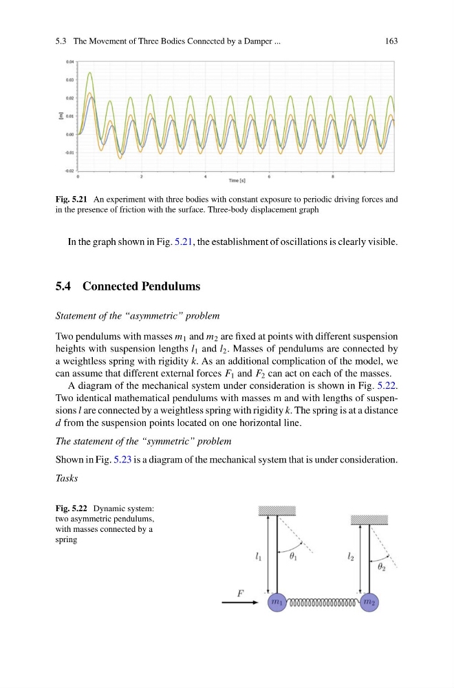
Fig. 5.21 An experiment with three bodies with constant exposure to periodic driving forces and
in the presence of friction with the surface. Three-body displacement graph
In the graph shown in Fig. 5.21, the establishment of oscillations is clearly visible.
5.4 Connected Pendulums
Statement of the “asymmetric” problem
Two pendulums with masses m 1 and m 2 are fixed at points with different suspension
heights with suspension lengths l 1 and l 2 . Masses of pendulums are connected by
a weightless spring with rigidity k. As an additional complication of the model, we
can assume that different external forces F 1 and F 2 can act on each of the masses.
A diagram of the mechanical system under consideration is shown in Fig. 5.22.
Two identical mathematical pendulums with masses m and with lengths of suspensions l are connected by a weightless spring with rigidity k. The spring is at a distance
d from the suspension points located on one horizontal line.
The statement of the “symmetric” problem
Shown in Fig. 5.23 is a diagram of the mechanical system that is under consideration.
Tasks
Fig. 5.22 Dynamic system:
two asymmetric pendulums,
with masses connected by a
spring
163
Fig. 5.21 An experiment with three bodies with constant exposure to periodic driving forces and
in the presence of friction with the surface. Three-body displacement graph
In the graph shown in Fig. 5.21, the establishment of oscillations is clearly visible.
5.4 Connected Pendulums
Statement of the “asymmetric” problem
Two pendulums with masses m 1 and m 2 are fixed at points with different suspension
heights with suspension lengths l 1 and l 2 . Masses of pendulums are connected by
a weightless spring with rigidity k. As an additional complication of the model, we
can assume that different external forces F 1 and F 2 can act on each of the masses.
A diagram of the mechanical system under consideration is shown in Fig. 5.22.
Two identical mathematical pendulums with masses m and with lengths of suspensions l are connected by a weightless spring with rigidity k. The spring is at a distance
d from the suspension points located on one horizontal line.
The statement of the “symmetric” problem
Shown in Fig. 5.23 is a diagram of the mechanical system that is under consideration.
Tasks
Fig. 5.22 Dynamic system:
two asymmetric pendulums,
with masses connected by a
spring