

3. Image acquisition at 5 s intervals (see Note 12).
4. Images should be captured as 16-bit images.
5. Perfuse control and experimental solution for 10 and 5 min,
respectively, by changing input solution manually.
3.6 Image Analysis
Acquired images are processed and analyzed using Fiji (https://fiji.
sc/) and Excel software (Microsoft).
3.6.1 Background
Subtraction
1. Open the sequential image file by Fiji software.
2. Choose any region of interest (ROI) where there is no plant
and measure the average fluorescence intensity within the ROI
(Use selection tool).
3. Subtract the average fluorescence intensity of the background
ROI from all sequential data (Image > Adjust > Brightness/
Contrast > Set Display Range > Set minimum displayed value
(¼background intensity) > Fill checkbox, “Propagate to all
other open images” > OK).
Liquid medium
+ stimulant/analyte
Microscope lens
Perfusion chamber
assembled to the holder
Withdraw
200 µL/min lane
A
B
C
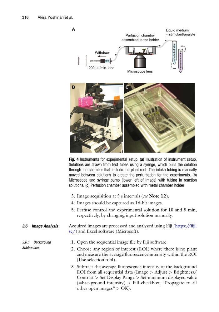
Fig. 4 Instruments for experimental setup. (a) Illustration of instrument setup.
Solutions are drawn from test tubes using a syringe, which pulls the solution
through the chamber that include the plant root. The intake tubing is manually
moved between solutions to create the perturbation for the experiments. (b)
Microscope and syringe pump (lower left of image) with tubing in reaction
solutions. (c) Perfusion chamber assembled with metal chamber holder
316
Akira Yoshinari et al.
4. Images should be captured as 16-bit images.
5. Perfuse control and experimental solution for 10 and 5 min,
respectively, by changing input solution manually.
3.6 Image Analysis
Acquired images are processed and analyzed using Fiji (https://fiji.
sc/) and Excel software (Microsoft).
3.6.1 Background
Subtraction
1. Open the sequential image file by Fiji software.
2. Choose any region of interest (ROI) where there is no plant
and measure the average fluorescence intensity within the ROI
(Use selection tool).
3. Subtract the average fluorescence intensity of the background
ROI from all sequential data (Image > Adjust > Brightness/
Contrast > Set Display Range > Set minimum displayed value
(¼background intensity) > Fill checkbox, “Propagate to all
other open images” > OK).
Liquid medium
+ stimulant/analyte
Microscope lens
Perfusion chamber
assembled to the holder
Withdraw
200 µL/min lane
A
B
C
Fig. 4 Instruments for experimental setup. (a) Illustration of instrument setup.
Solutions are drawn from test tubes using a syringe, which pulls the solution
through the chamber that include the plant root. The intake tubing is manually
moved between solutions to create the perturbation for the experiments. (b)
Microscope and syringe pump (lower left of image) with tubing in reaction
solutions. (c) Perfusion chamber assembled with metal chamber holder
316
Akira Yoshinari et al.