

where the polyclonal antibodies specific for E. coli are tagged with fluorescent
secondary antibodies that are fixed to borosilicate glass fibers priorly treated with
silane for the output signal. A photodiode placed at one terminal of the glass fiber
monitors the optical changes taking place upon interaction with E. coli, the consequent changes in optical emission signals, the refractive index of glass fiber, and
eventually total internal reflection. This happens to be a simple and portable biosensor that requires improvement in sensitivity.
10.3.2 Surface Plasmon Resonance Biosensors
The real-time and label-free sensing of bioanalytes was achieved with surface
plasmon resonance-based biosensors. The optical phenomenon employed here is
accompanied by alteration of surface plasmon wave following the changes on the
sensor surface (mostly made of metals such as gold, silver, or copper) upon binding
of the target analytes with specificity (Homola 2003).
In this method of sensing, a prism-coupled system is employed as depicted in
Fig. 10.5 (Brindha et al. 2018b; Pi et al. 2016). The difference in signal observed in
this type of sensing is attributed to the alterations in the interfacial refractive index at
the top upon interaction with biomolecules.
Direct detection of Campylobacter jejuni was achieved with a sensor surface
made of a gold chip which was coated with polyclonal antibodies specific to
C. jejuni. This type of direct biosensing of C. jejuni resulted in a relatively higher
limit of detection of 8 Â 10
6 cfu/ml (Masdor et al. 2017). In order to improve the
detection limits, the sandwich assay was developed that resulted in detecting as low
as 4 Â 10
4 cfu/ml. This proved as an efficient and alternate method to replace the
traditional enzyme-linked immunosorbent assays with a limit of detection of 10
6
–
10
7 cfu/ml.
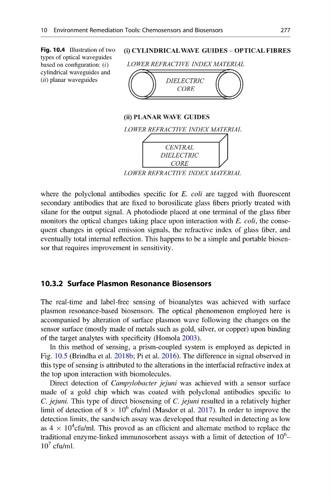
(i) CYLINDRICAL WAVE GUIDES – OPTICAL FIBRES
DIELECTRIC
CORE
LOWER REFRACTIVE INDEX MATERIAL
(ii) PLANAR WAVE GUIDES
LOWER REFRACTIVE INDEX MATERIAL
CENTRAL
DIELECTRIC
CORE
LOWER REFRACTIVE INDEX MATERIAL
Fig. 10.4 Illustration of two
types of optical waveguides
based on configuration: (i)
cylindrical waveguides and
(ii) planar waveguides
10 Environment Remediation Tools: Chemosensors and Biosensors
277
secondary antibodies that are fixed to borosilicate glass fibers priorly treated with
silane for the output signal. A photodiode placed at one terminal of the glass fiber
monitors the optical changes taking place upon interaction with E. coli, the consequent changes in optical emission signals, the refractive index of glass fiber, and
eventually total internal reflection. This happens to be a simple and portable biosensor that requires improvement in sensitivity.
10.3.2 Surface Plasmon Resonance Biosensors
The real-time and label-free sensing of bioanalytes was achieved with surface
plasmon resonance-based biosensors. The optical phenomenon employed here is
accompanied by alteration of surface plasmon wave following the changes on the
sensor surface (mostly made of metals such as gold, silver, or copper) upon binding
of the target analytes with specificity (Homola 2003).
In this method of sensing, a prism-coupled system is employed as depicted in
Fig. 10.5 (Brindha et al. 2018b; Pi et al. 2016). The difference in signal observed in
this type of sensing is attributed to the alterations in the interfacial refractive index at
the top upon interaction with biomolecules.
Direct detection of Campylobacter jejuni was achieved with a sensor surface
made of a gold chip which was coated with polyclonal antibodies specific to
C. jejuni. This type of direct biosensing of C. jejuni resulted in a relatively higher
limit of detection of 8 Â 10
6 cfu/ml (Masdor et al. 2017). In order to improve the
detection limits, the sandwich assay was developed that resulted in detecting as low
as 4 Â 10
4 cfu/ml. This proved as an efficient and alternate method to replace the
traditional enzyme-linked immunosorbent assays with a limit of detection of 10
6
–
10
7 cfu/ml.
(i) CYLINDRICAL WAVE GUIDES – OPTICAL FIBRES
DIELECTRIC
CORE
LOWER REFRACTIVE INDEX MATERIAL
(ii) PLANAR WAVE GUIDES
LOWER REFRACTIVE INDEX MATERIAL
CENTRAL
DIELECTRIC
CORE
LOWER REFRACTIVE INDEX MATERIAL
Fig. 10.4 Illustration of two
types of optical waveguides
based on configuration: (i)
cylindrical waveguides and
(ii) planar waveguides
10 Environment Remediation Tools: Chemosensors and Biosensors
277