

As in the first stage, the second stage wetland is also lined with an HDPE
membrane of 1.5 mm thickness, with a layer of compacted clay sand placed below
the HPDE liner. Artificial aeration is provided in this wetland bed through a network
of aeration drip lines placed at the bottom of the bed connected to a side channel
blower (one working, one standby) that delivers an airflow 330 m
3
/h. An alternate
operation of the two blowers is conducted every 24 h to avoid any mechanical
problems due to ambient air condensation when the blower is off for a long time
period. The first blower supplies air continuously for 24 h to the whole network of
pipe and drip lines at the bottom of the ACW, while the second blower is off. An
automatic switch alternates daily the blower operation. The aeration pipes are placed
at short distances at the bottom, providing small bubbles of air in the saturated gravel
layer to enhance the aerobic processes, such as organic matter biodegradation and
nitrification. The water level is adjustable through a water level control device and is
set few centimetres below the surface of the gravel layer of the constructed wetland,
so that no water surface is exposed to the atmosphere and in order to eliminate
mosquitos and bad odour issues. The ACW effluent is collected through a perforated
pipe placed at the bottom of the bed above the HDPE liner along the downstream
width side.
Both CW stages are planted with native wetland plant species, which can be
found in the country. The first stage VFCW bed is planted with common reeds
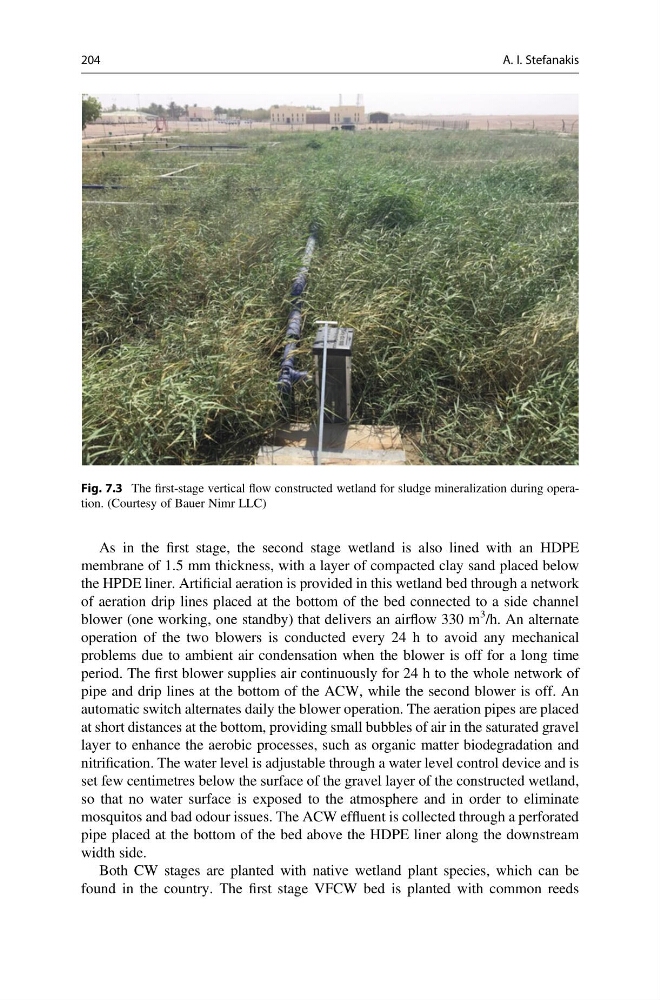
Fig. 7.3 The first-stage vertical flow constructed wetland for sludge mineralization during operation. (Courtesy of Bauer Nimr LLC)
204
A. I. Stefanakis
membrane of 1.5 mm thickness, with a layer of compacted clay sand placed below
the HPDE liner. Artificial aeration is provided in this wetland bed through a network
of aeration drip lines placed at the bottom of the bed connected to a side channel
blower (one working, one standby) that delivers an airflow 330 m
3
/h. An alternate
operation of the two blowers is conducted every 24 h to avoid any mechanical
problems due to ambient air condensation when the blower is off for a long time
period. The first blower supplies air continuously for 24 h to the whole network of
pipe and drip lines at the bottom of the ACW, while the second blower is off. An
automatic switch alternates daily the blower operation. The aeration pipes are placed
at short distances at the bottom, providing small bubbles of air in the saturated gravel
layer to enhance the aerobic processes, such as organic matter biodegradation and
nitrification. The water level is adjustable through a water level control device and is
set few centimetres below the surface of the gravel layer of the constructed wetland,
so that no water surface is exposed to the atmosphere and in order to eliminate
mosquitos and bad odour issues. The ACW effluent is collected through a perforated
pipe placed at the bottom of the bed above the HDPE liner along the downstream
width side.
Both CW stages are planted with native wetland plant species, which can be
found in the country. The first stage VFCW bed is planted with common reeds
Fig. 7.3 The first-stage vertical flow constructed wetland for sludge mineralization during operation. (Courtesy of Bauer Nimr LLC)
204
A. I. Stefanakis