

process is a robust mould or stamp. Further requirement for optical waveguide
fabrication is an extremely low sidewall surface roughness of the mould or stamp
(<30 nm) to guarantee low scattering losses. Taking advantage of the high
mechanical and chemical resistance, SU-8 photoresist patterns were employed
directly as mould providing high structure fidelity. In this process, no special
anti-adhesion layer was required to separate the PDMS material from the mould.
The fabrication started by filling the waveguide grooves with the liquid core
polymer, which was done using a blading process (see Fig. 13.2a). For reliably
controlled process conditions, a stencil printer was used, which was originally
implemented in surface-mount technology. The blading velocity is motor controlled. The choice of PMMA or polyoxymethylene (POM) as blading material was
guided by the demands of the blade softness, flexibility and long-lasting
hard-wearing. To prevent the core material from creeping into the areas outside
the waveguides, laser cut metal squeegee shims are used during blading. The first
process step is finalized with thermal curing of the core polymer. Finally, the
squeegee shim was removed from the mould. For the second step, liquid cladding
material is poured into the whole mould area (see Fig. 13.2b). After curing at 70 °C
for 30 min, cladding and core were separated from the mould (Fig. 13.2c). This
half-open structure is then filled with a second cladding material (Fig. 13.2d). With
a final curing step at 70 °C for 60 min, the production process of the waveguiding
laminate was terminated, and after this, the optical layer can be packaged.
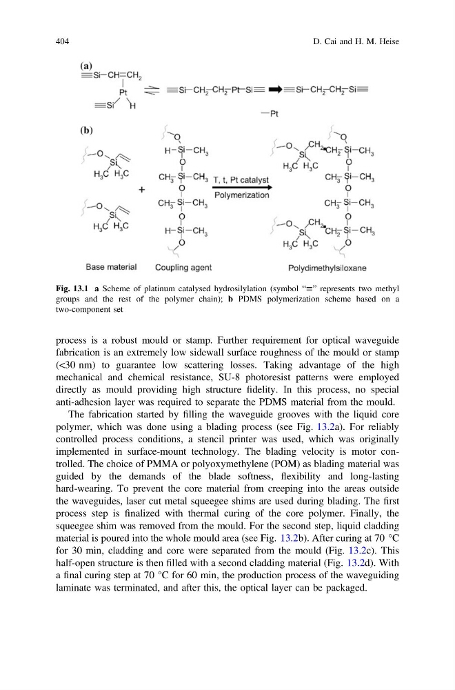
Fig. 13.1 a Scheme of platinum catalysed hydrosilylation (symbol “” represents two methyl
groups and the rest of the polymer chain); b PDMS polymerization scheme based on a
two-component set
404
D. Cai and H. M. Heise
fabrication is an extremely low sidewall surface roughness of the mould or stamp
(<30 nm) to guarantee low scattering losses. Taking advantage of the high
mechanical and chemical resistance, SU-8 photoresist patterns were employed
directly as mould providing high structure fidelity. In this process, no special
anti-adhesion layer was required to separate the PDMS material from the mould.
The fabrication started by filling the waveguide grooves with the liquid core
polymer, which was done using a blading process (see Fig. 13.2a). For reliably
controlled process conditions, a stencil printer was used, which was originally
implemented in surface-mount technology. The blading velocity is motor controlled. The choice of PMMA or polyoxymethylene (POM) as blading material was
guided by the demands of the blade softness, flexibility and long-lasting
hard-wearing. To prevent the core material from creeping into the areas outside
the waveguides, laser cut metal squeegee shims are used during blading. The first
process step is finalized with thermal curing of the core polymer. Finally, the
squeegee shim was removed from the mould. For the second step, liquid cladding
material is poured into the whole mould area (see Fig. 13.2b). After curing at 70 °C
for 30 min, cladding and core were separated from the mould (Fig. 13.2c). This
half-open structure is then filled with a second cladding material (Fig. 13.2d). With
a final curing step at 70 °C for 60 min, the production process of the waveguiding
laminate was terminated, and after this, the optical layer can be packaged.
Fig. 13.1 a Scheme of platinum catalysed hydrosilylation (symbol “” represents two methyl
groups and the rest of the polymer chain); b PDMS polymerization scheme based on a
two-component set
404
D. Cai and H. M. Heise