

102
6 Applications
6.6 River, Urban, Farm
We have been clear about the difference between water resource and water use
(Sect. 2.1). In this case, we present a river section as a WUS that receives water from
upstream (inflows) and supplies water (outflows) to an urban area and an irrigated
region while guaranteeing a predefined minimum amount of water for downstream.
This example is taken from the Open Access paper of Ahmad and Haie (2018),
which analyses the situation of the Kano River in Nigeria (an upper tributary of lake
Chad) and the impacts of population growth and climate change until 2050. Here,
we describe some general aspects and invite those interested to refer to the paper for
more details.
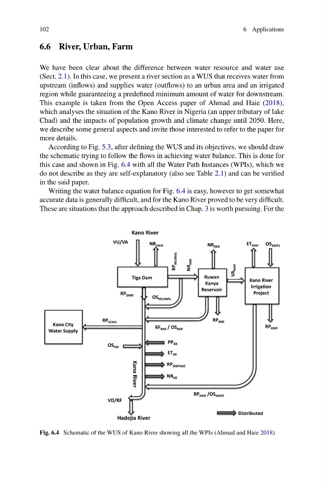
According to Fig. 5.3, after defining the WUS and its objectives, we should draw
the schematic trying to follow the flows in achieving water balance. This is done for
this case and shown in Fig. 6.4 with all the Water Path Instances (WPIs), which we
do not describe as they are self-explanatory (also see Table 2.1) and can be verified
in the said paper.
Writing the water balance equation for Fig. 6.4 is easy, however to get somewhat
accurate data is generally difficult, and for the Kano River proved to be very difficult.
These are situations that the approach described in Chap. 3 is worth pursuing. For the
Kano River
IrrigaƟon
Project
RP KRIP /OS KRIP2
RP KRIP
ET KRIP
Ruwan
Kanya
Reservoir
Kano River
Hadejia River
Tiga Dam
RF RKR / OS RKR
NR DAM
NR RKR
OS KRIP1
Kano River
RP RKR
Kano City
Water Supply
ET KR
OS IRCANAL
NR
RKR
VA
KRIP
RP
IRCANAL
VD/RF
VU/VA
OS KM
RP KCWS
RP SEEPAGE
NR KR
RP DAM
PP KR
Distributed
Fig. 6.4 Schematic of the WUS of Kano River showing all the WPIs (Ahmad and Haie 2018)
6 Applications
6.6 River, Urban, Farm
We have been clear about the difference between water resource and water use
(Sect. 2.1). In this case, we present a river section as a WUS that receives water from
upstream (inflows) and supplies water (outflows) to an urban area and an irrigated
region while guaranteeing a predefined minimum amount of water for downstream.
This example is taken from the Open Access paper of Ahmad and Haie (2018),
which analyses the situation of the Kano River in Nigeria (an upper tributary of lake
Chad) and the impacts of population growth and climate change until 2050. Here,
we describe some general aspects and invite those interested to refer to the paper for
more details.
According to Fig. 5.3, after defining the WUS and its objectives, we should draw
the schematic trying to follow the flows in achieving water balance. This is done for
this case and shown in Fig. 6.4 with all the Water Path Instances (WPIs), which we
do not describe as they are self-explanatory (also see Table 2.1) and can be verified
in the said paper.
Writing the water balance equation for Fig. 6.4 is easy, however to get somewhat
accurate data is generally difficult, and for the Kano River proved to be very difficult.
These are situations that the approach described in Chap. 3 is worth pursuing. For the
Kano River
IrrigaƟon
Project
RP KRIP /OS KRIP2
RP KRIP
ET KRIP
Ruwan
Kanya
Reservoir
Kano River
Hadejia River
Tiga Dam
RF RKR / OS RKR
NR DAM
NR RKR
OS KRIP1
Kano River
RP RKR
Kano City
Water Supply
ET KR
OS IRCANAL
NR
RKR
VA
KRIP
RP
IRCANAL
VD/RF
VU/VA
OS KM
RP KCWS
RP SEEPAGE
NR KR
RP DAM
PP KR
Distributed
Fig. 6.4 Schematic of the WUS of Kano River showing all the WPIs (Ahmad and Haie 2018)