

3.1 Sample
Preparation
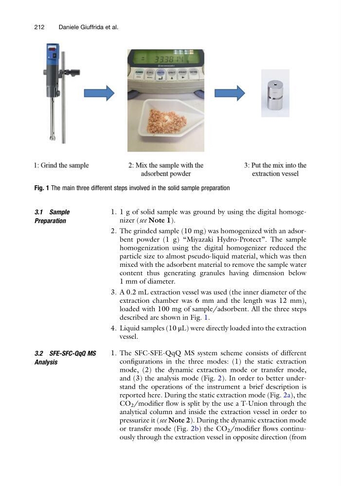
1. 1 g of solid sample was ground by using the digital homogenizer (see Note 1).
2. The grinded sample (10 mg) was homogenized with an adsorbent powder (1 g) “Miyazaki Hydro-Protect”. The sample
homogenization using the digital homogenizer reduced the
particle size to almost pseudo-liquid material, which was then
mixed with the adsorbent material to remove the sample water
content thus generating granules having dimension below
1 mm of diameter.
3. A 0.2 mL extraction vessel was used (the inner diameter of the
extraction chamber was 6 mm and the length was 12 mm),
loaded with 100 mg of sample/adsorbent. All the three steps
described are shown in Fig. 1.
4. Liquid samples (10 μL) were directly loaded into the extraction
vessel.
3.2 SFE-SFC-QqQ MS
Analysis
1. The SFC-SFE-QqQ MS system scheme consists of different
configurations in the three modes: (1) the static extraction
mode, (2) the dynamic extraction mode or transfer mode,
and (3) the analysis mode (Fig. 2). In order to better understand the operations of the instrument a brief description is
reported here. During the static extraction mode (Fig. 2a), the
CO 2 /modifier flow is split by the use a T-Union through the
analytical column and inside the extraction vessel in order to
pressurize it (see Note 2). During the dynamic extraction mode
or transfer mode (Fig. 2b) the CO 2 /modifier flows continuously through the extraction vessel in opposite direction (from
Fig. 1 The main three different steps involved in the solid sample preparation
212
Daniele Giuffrida et al.
Preparation
1. 1 g of solid sample was ground by using the digital homogenizer (see Note 1).
2. The grinded sample (10 mg) was homogenized with an adsorbent powder (1 g) “Miyazaki Hydro-Protect”. The sample
homogenization using the digital homogenizer reduced the
particle size to almost pseudo-liquid material, which was then
mixed with the adsorbent material to remove the sample water
content thus generating granules having dimension below
1 mm of diameter.
3. A 0.2 mL extraction vessel was used (the inner diameter of the
extraction chamber was 6 mm and the length was 12 mm),
loaded with 100 mg of sample/adsorbent. All the three steps
described are shown in Fig. 1.
4. Liquid samples (10 μL) were directly loaded into the extraction
vessel.
3.2 SFE-SFC-QqQ MS
Analysis
1. The SFC-SFE-QqQ MS system scheme consists of different
configurations in the three modes: (1) the static extraction
mode, (2) the dynamic extraction mode or transfer mode,
and (3) the analysis mode (Fig. 2). In order to better understand the operations of the instrument a brief description is
reported here. During the static extraction mode (Fig. 2a), the
CO 2 /modifier flow is split by the use a T-Union through the
analytical column and inside the extraction vessel in order to
pressurize it (see Note 2). During the dynamic extraction mode
or transfer mode (Fig. 2b) the CO 2 /modifier flows continuously through the extraction vessel in opposite direction (from
Fig. 1 The main three different steps involved in the solid sample preparation
212
Daniele Giuffrida et al.