

48
T. B. Asafa et al.
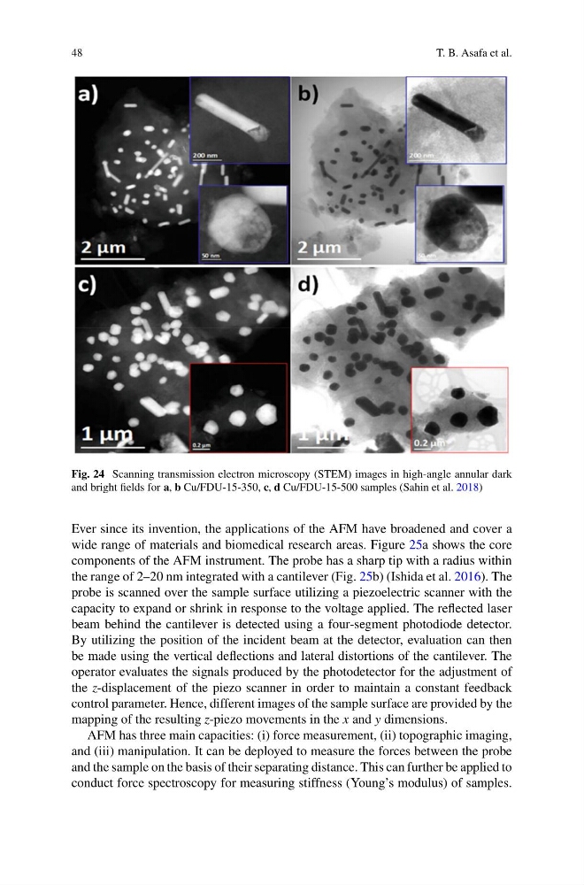
Fig. 24 Scanning transmission electron microscopy (STEM) images in high-angle annular dark
and bright fields for a, b Cu/FDU-15-350, c, d Cu/FDU-15-500 samples (Sahin et al. 2018)
Ever since its invention, the applications of the AFM have broadened and cover a
wide range of materials and biomedical research areas. Figure 25a shows the core
components of the AFM instrument. The probe has a sharp tip with a radius within
the range of 2–20 nm integrated with a cantilever (Fig. 25b) (Ishida et al. 2016). The
probe is scanned over the sample surface utilizing a piezoelectric scanner with the
capacity to expand or shrink in response to the voltage applied. The reflected laser
beam behind the cantilever is detected using a four-segment photodiode detector.
By utilizing the position of the incident beam at the detector, evaluation can then
be made using the vertical deflections and lateral distortions of the cantilever. The
operator evaluates the signals produced by the photodetector for the adjustment of
the z-displacement of the piezo scanner in order to maintain a constant feedback
control parameter. Hence, different images of the sample surface are provided by the
mapping of the resulting z-piezo movements in the x and y dimensions.
AFM has three main capacities: (i) force measurement, (ii) topographic imaging,
and (iii) manipulation. It can be deployed to measure the forces between the probe
and the sample on the basis of their separating distance. This can further be applied to
conduct force spectroscopy for measuring stiffness (Young’s modulus) of samples.
T. B. Asafa et al.
Fig. 24 Scanning transmission electron microscopy (STEM) images in high-angle annular dark
and bright fields for a, b Cu/FDU-15-350, c, d Cu/FDU-15-500 samples (Sahin et al. 2018)
Ever since its invention, the applications of the AFM have broadened and cover a
wide range of materials and biomedical research areas. Figure 25a shows the core
components of the AFM instrument. The probe has a sharp tip with a radius within
the range of 2–20 nm integrated with a cantilever (Fig. 25b) (Ishida et al. 2016). The
probe is scanned over the sample surface utilizing a piezoelectric scanner with the
capacity to expand or shrink in response to the voltage applied. The reflected laser
beam behind the cantilever is detected using a four-segment photodiode detector.
By utilizing the position of the incident beam at the detector, evaluation can then
be made using the vertical deflections and lateral distortions of the cantilever. The
operator evaluates the signals produced by the photodetector for the adjustment of
the z-displacement of the piezo scanner in order to maintain a constant feedback
control parameter. Hence, different images of the sample surface are provided by the
mapping of the resulting z-piezo movements in the x and y dimensions.
AFM has three main capacities: (i) force measurement, (ii) topographic imaging,
and (iii) manipulation. It can be deployed to measure the forces between the probe
and the sample on the basis of their separating distance. This can further be applied to
conduct force spectroscopy for measuring stiffness (Young’s modulus) of samples.