

86
N. Sharma and R. Choudhary
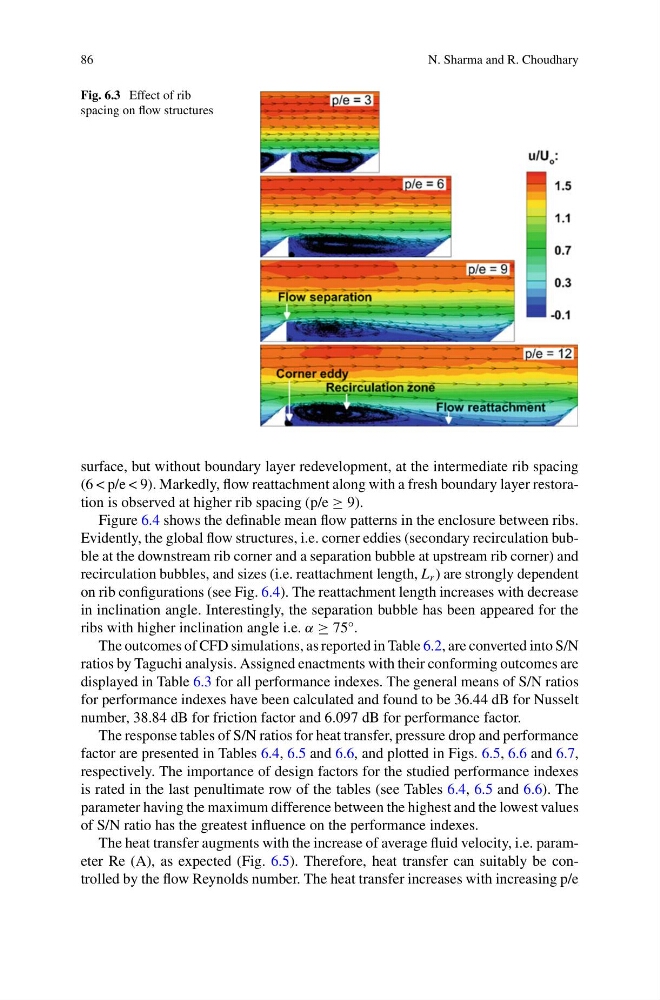
Fig. 6.3 Effect of rib
spacing on flow structures
surface, but without boundary layer redevelopment, at the intermediate rib spacing
(6 < p/e < 9). Markedly, flow reattachment along with a fresh boundary layer restoration is observed at higher rib spacing (p/e ≥ 9).
Figure 6.4 shows the definable mean flow patterns in the enclosure between ribs.
Evidently, the global flow structures, i.e. corner eddies (secondary recirculation bubble at the downstream rib corner and a separation bubble at upstream rib corner) and
recirculation bubbles, and sizes (i.e. reattachment length, L r ) are strongly dependent
on rib configurations (see Fig. 6.4). The reattachment length increases with decrease
in inclination angle. Interestingly, the separation bubble has been appeared for the
ribs with higher inclination angle i.e. α ≥ 75°.
The outcomes of CFD simulations, as reported in Table 6.2, are converted into S/N
ratios by Taguchi analysis. Assigned enactments with their conforming outcomes are
displayed in Table 6.3 for all performance indexes. The general means of S/N ratios
for performance indexes have been calculated and found to be 36.44 dB for Nusselt
number, 38.84 dB for friction factor and 6.097 dB for performance factor.
The response tables of S/N ratios for heat transfer, pressure drop and performance
factor are presented in Tables 6.4, 6.5 and 6.6, and plotted in Figs. 6.5, 6.6 and 6.7,
respectively. The importance of design factors for the studied performance indexes
is rated in the last penultimate row of the tables (see Tables 6.4, 6.5 and 6.6). The
parameter having the maximum difference between the highest and the lowest values
of S/N ratio has the greatest influence on the performance indexes.
The heat transfer augments with the increase of average fluid velocity, i.e. parameter Re (A), as expected (Fig. 6.5). Therefore, heat transfer can suitably be controlled by the flow Reynolds number. The heat transfer increases with increasing p/e
N. Sharma and R. Choudhary
Fig. 6.3 Effect of rib
spacing on flow structures
surface, but without boundary layer redevelopment, at the intermediate rib spacing
(6 < p/e < 9). Markedly, flow reattachment along with a fresh boundary layer restoration is observed at higher rib spacing (p/e ≥ 9).
Figure 6.4 shows the definable mean flow patterns in the enclosure between ribs.
Evidently, the global flow structures, i.e. corner eddies (secondary recirculation bubble at the downstream rib corner and a separation bubble at upstream rib corner) and
recirculation bubbles, and sizes (i.e. reattachment length, L r ) are strongly dependent
on rib configurations (see Fig. 6.4). The reattachment length increases with decrease
in inclination angle. Interestingly, the separation bubble has been appeared for the
ribs with higher inclination angle i.e. α ≥ 75°.
The outcomes of CFD simulations, as reported in Table 6.2, are converted into S/N
ratios by Taguchi analysis. Assigned enactments with their conforming outcomes are
displayed in Table 6.3 for all performance indexes. The general means of S/N ratios
for performance indexes have been calculated and found to be 36.44 dB for Nusselt
number, 38.84 dB for friction factor and 6.097 dB for performance factor.
The response tables of S/N ratios for heat transfer, pressure drop and performance
factor are presented in Tables 6.4, 6.5 and 6.6, and plotted in Figs. 6.5, 6.6 and 6.7,
respectively. The importance of design factors for the studied performance indexes
is rated in the last penultimate row of the tables (see Tables 6.4, 6.5 and 6.6). The
parameter having the maximum difference between the highest and the lowest values
of S/N ratio has the greatest influence on the performance indexes.
The heat transfer augments with the increase of average fluid velocity, i.e. parameter Re (A), as expected (Fig. 6.5). Therefore, heat transfer can suitably be controlled by the flow Reynolds number. The heat transfer increases with increasing p/e