

11 PCM-Metal Foam Composite Systems for Solar Energy Storage
217
• After the spheres are generated, the generated geometry needs to be mapped to a
metal volume fraction parameter, (ϕ), to differentiate the metal and PCM in the
discretized problem domain. To do this, the entire domain is divided into a very
fine uniform grid structure. The grid points which are within any of the spheres
are assigned a value of 0 and the grid points outside all the spheres are assigned
a value of 1. Subsequently, a new relatively coarse mesh is generated. Each grid
point in the new mesh correspond to several grid points in the original mesh. The
value of metal volume fraction (ϕ) is calculated for each grid point of the new
mesh by summing all the values of 1 and 0 for the corresponding grid points in the
original mesh and dividing by the number of original grid points corresponding to
a single grid point in the new mesh.
• The value of ϕ for all the grid points in the new mesh denote the metal fraction
for the entire geometry. This new mesh is used for all the subsequent calculations
and the old mesh is discarded. The volume fraction of PCM at each node is equal
to (1 − ϕ).
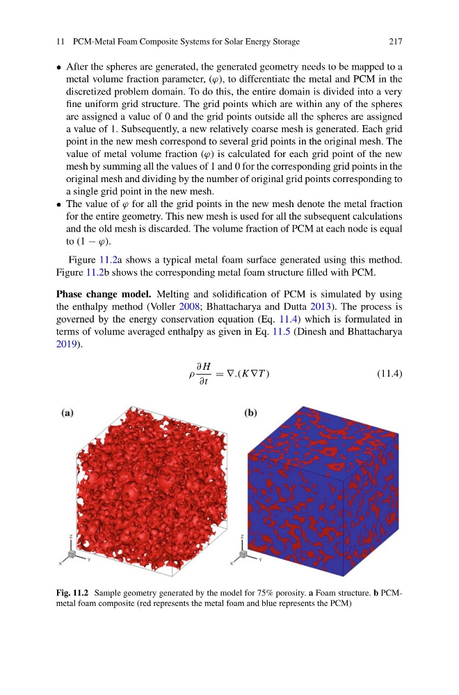
Figure 11.2a shows a typical metal foam surface generated using this method.
Figure 11.2b shows the corresponding metal foam structure filled with PCM.
Phase change model. Melting and solidification of PCM is simulated by using
the enthalpy method (Voller 2008; Bhattacharya and Dutta 2013). The process is
governed by the energy conservation equation (Eq. 11.4) which is formulated in
terms of volume averaged enthalpy as given in Eq. 11.5 (Dinesh and Bhattacharya
2019).
ρ
∂ H
∂t
= ∇.(K ∇T )
(11.4)
Fig. 11.2 Sample geometry generated by the model for 75% porosity. a Foam structure. b PCMmetal foam composite (red represents the metal foam and blue represents the PCM)
217
• After the spheres are generated, the generated geometry needs to be mapped to a
metal volume fraction parameter, (ϕ), to differentiate the metal and PCM in the
discretized problem domain. To do this, the entire domain is divided into a very
fine uniform grid structure. The grid points which are within any of the spheres
are assigned a value of 0 and the grid points outside all the spheres are assigned
a value of 1. Subsequently, a new relatively coarse mesh is generated. Each grid
point in the new mesh correspond to several grid points in the original mesh. The
value of metal volume fraction (ϕ) is calculated for each grid point of the new
mesh by summing all the values of 1 and 0 for the corresponding grid points in the
original mesh and dividing by the number of original grid points corresponding to
a single grid point in the new mesh.
• The value of ϕ for all the grid points in the new mesh denote the metal fraction
for the entire geometry. This new mesh is used for all the subsequent calculations
and the old mesh is discarded. The volume fraction of PCM at each node is equal
to (1 − ϕ).
Figure 11.2a shows a typical metal foam surface generated using this method.
Figure 11.2b shows the corresponding metal foam structure filled with PCM.
Phase change model. Melting and solidification of PCM is simulated by using
the enthalpy method (Voller 2008; Bhattacharya and Dutta 2013). The process is
governed by the energy conservation equation (Eq. 11.4) which is formulated in
terms of volume averaged enthalpy as given in Eq. 11.5 (Dinesh and Bhattacharya
2019).
ρ
∂ H
∂t
= ∇.(K ∇T )
(11.4)
Fig. 11.2 Sample geometry generated by the model for 75% porosity. a Foam structure. b PCMmetal foam composite (red represents the metal foam and blue represents the PCM)