

160
Md. A. Islam and B. B. Saha
System Runtime
A cooling system is not always running. Either the system is turned off by the user or
the system turns itself off when it reaches the desired temperature. Hence, a certain
runtime is considered for this assessment.
9.3.1.2 Assessment Results
In order to determine the indirect emission, electricity consumption is required.
Electricity consumption depends on the COP of the system, which is ultimately
obtained from the thermodynamic properties of the refrigerant by using REFPROP
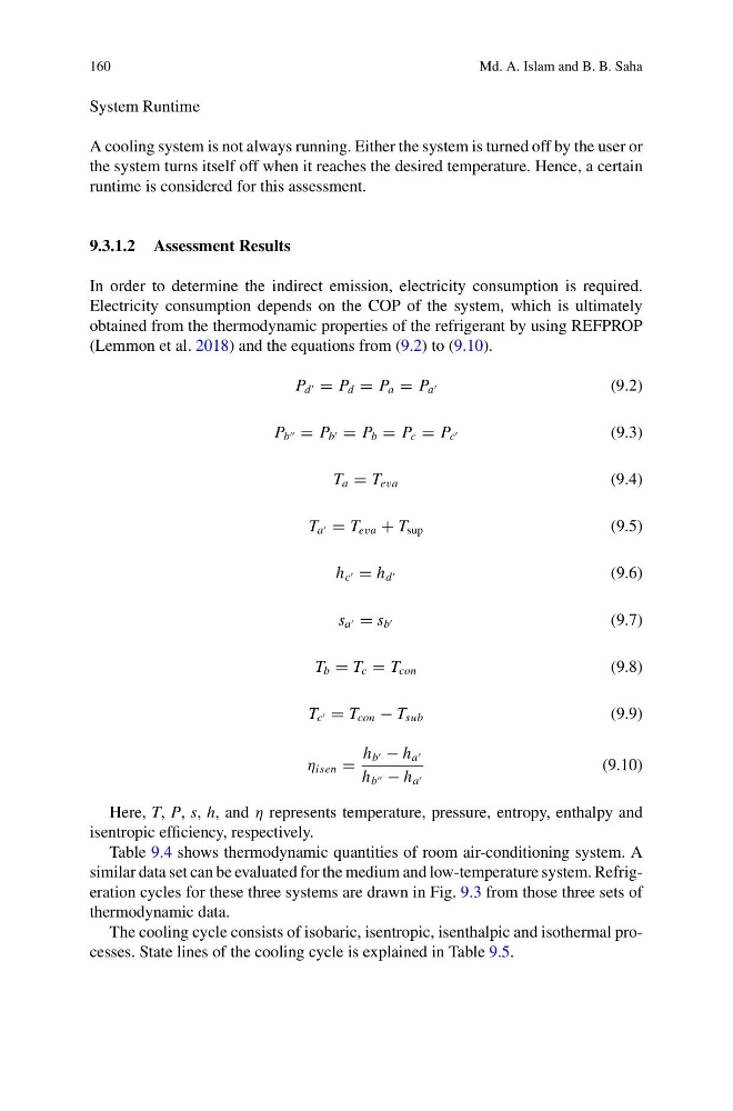
(Lemmon et al. 2018) and the equations from (9.2) to (9.10).
P d = P d = P a = P a
(9.2)
P b = P b = P b = P c = P c
(9.3)
T a = T eva
(9.4)
T a = T eva + T sup
(9.5)
h c = h d
(9.6)
s a = s b
(9.7)
T b = T c = T con
(9.8)
T c = T con − T sub
(9.9)
η isen =
h b − h a
h b − h a
(9.10)
Here, T, P, s, h, and η represents temperature, pressure, entropy, enthalpy and
isentropic efficiency, respectively.
Table 9.4 shows thermodynamic quantities of room air-conditioning system. A
similar data set can be evaluated for the medium and low-temperature system. Refrigeration cycles for these three systems are drawn in Fig. 9.3 from those three sets of
thermodynamic data.
The cooling cycle consists of isobaric, isentropic, isenthalpic and isothermal processes. State lines of the cooling cycle is explained in Table 9.5.
Md. A. Islam and B. B. Saha
System Runtime
A cooling system is not always running. Either the system is turned off by the user or
the system turns itself off when it reaches the desired temperature. Hence, a certain
runtime is considered for this assessment.
9.3.1.2 Assessment Results
In order to determine the indirect emission, electricity consumption is required.
Electricity consumption depends on the COP of the system, which is ultimately
obtained from the thermodynamic properties of the refrigerant by using REFPROP
(Lemmon et al. 2018) and the equations from (9.2) to (9.10).
P d = P d = P a = P a
(9.2)
P b = P b = P b = P c = P c
(9.3)
T a = T eva
(9.4)
T a = T eva + T sup
(9.5)
h c = h d
(9.6)
s a = s b
(9.7)
T b = T c = T con
(9.8)
T c = T con − T sub
(9.9)
η isen =
h b − h a
h b − h a
(9.10)
Here, T, P, s, h, and η represents temperature, pressure, entropy, enthalpy and
isentropic efficiency, respectively.
Table 9.4 shows thermodynamic quantities of room air-conditioning system. A
similar data set can be evaluated for the medium and low-temperature system. Refrigeration cycles for these three systems are drawn in Fig. 9.3 from those three sets of
thermodynamic data.
The cooling cycle consists of isobaric, isentropic, isenthalpic and isothermal processes. State lines of the cooling cycle is explained in Table 9.5.