

8 Solar Thermal-Powered Adsorption Chiller
139
and for Bed 2,
MC p
bed,ads
dT bed,ads
dt
= M bed h ads
dw
dt
(8.49)
Bed Equations During Heat Recovery
In the heat recovery stage, the beds are isolated from evaporator, condenser and also
from each other. As a result, there is no flow of water vapor through the beds. The
temperature of hot water at the outlet remains the same as it is at the inlet since there
is no flow of hot water through the bed (see Fig. 8.9). The cooling water extracts heat
from the desorbed bed (Bed 1) and heats up the adsorbed bed (Bed 2) on its way to
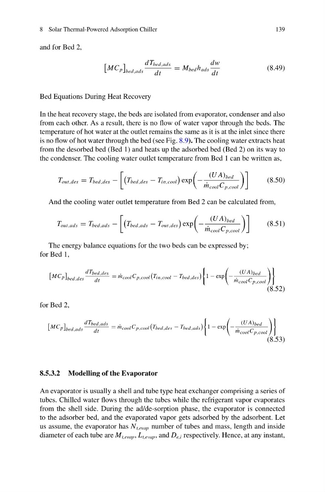
the condenser. The cooling water outlet temperature from Bed 1 can be written as,
T out,des = T bed,des −
T bed,des − T in,cool
exp
−
(U A) bed
˙
m cool C p,cool
(8.50)
And the cooling water outlet temperature from Bed 2 can be calculated from,
T out,ads = T bed,ads −
T bed,ads − T out,des
exp
−
(U A) bed
˙
m cool C p,cool
(8.51)
The energy balance equations for the two beds can be expressed by;
for Bed 1,
MC p
bed,des
dT bed,des
dt
= ˙
m cool C p,cool
T in,cool − T bed,des
1 − exp
−
(U A) bed
˙
m cool C p,cool
(8.52)
for Bed 2,
MC p
bed,ads
dT bed,ads
dt
= ˙
m cool C p,cool
T bed,des − T bed,ads
1 − exp
−
(U A) bed
˙
m cool C p,cool
(8.53)
8.5.3.2 Modelling of the Evaporator
An evaporator is usually a shell and tube type heat exchanger comprising a series of
tubes. Chilled water flows through the tubes while the refrigerant vapor evaporates
from the shell side. During the ad/de-sorption phase, the evaporator is connected
to the adsorber bed, and the evaporated vapor gets adsorbed by the adsorbent. Let
us assume, the evaporator has N t,evap number of tubes and mass, length and inside
diameter of each tube are M t,evap , L t,evap , and D e,i respectively. Hence, at any instant,
139
and for Bed 2,
MC p
bed,ads
dT bed,ads
dt
= M bed h ads
dw
dt
(8.49)
Bed Equations During Heat Recovery
In the heat recovery stage, the beds are isolated from evaporator, condenser and also
from each other. As a result, there is no flow of water vapor through the beds. The
temperature of hot water at the outlet remains the same as it is at the inlet since there
is no flow of hot water through the bed (see Fig. 8.9). The cooling water extracts heat
from the desorbed bed (Bed 1) and heats up the adsorbed bed (Bed 2) on its way to
the condenser. The cooling water outlet temperature from Bed 1 can be written as,
T out,des = T bed,des −
T bed,des − T in,cool
exp
−
(U A) bed
˙
m cool C p,cool
(8.50)
And the cooling water outlet temperature from Bed 2 can be calculated from,
T out,ads = T bed,ads −
T bed,ads − T out,des
exp
−
(U A) bed
˙
m cool C p,cool
(8.51)
The energy balance equations for the two beds can be expressed by;
for Bed 1,
MC p
bed,des
dT bed,des
dt
= ˙
m cool C p,cool
T in,cool − T bed,des
1 − exp
−
(U A) bed
˙
m cool C p,cool
(8.52)
for Bed 2,
MC p
bed,ads
dT bed,ads
dt
= ˙
m cool C p,cool
T bed,des − T bed,ads
1 − exp
−
(U A) bed
˙
m cool C p,cool
(8.53)
8.5.3.2 Modelling of the Evaporator
An evaporator is usually a shell and tube type heat exchanger comprising a series of
tubes. Chilled water flows through the tubes while the refrigerant vapor evaporates
from the shell side. During the ad/de-sorption phase, the evaporator is connected
to the adsorber bed, and the evaporated vapor gets adsorbed by the adsorbent. Let
us assume, the evaporator has N t,evap number of tubes and mass, length and inside
diameter of each tube are M t,evap , L t,evap , and D e,i respectively. Hence, at any instant,