

8 Solar Thermal-Powered Adsorption Chiller
135
during the process of adsorption or desorption. And the last term indicates the sensible heat transfer between the heat transfer fluid and the respective component.
The solution of Eq. (8.33) provides the temperature T k of the heat exchanger
components. But that requires the outlet temperature T out to be known. In order to
determine T out , the log mean temperature difference (LMTD) of the energy balance
equation for heat transfer fluid is employed. According to that method, the amount
of heat transfer,
˙
Q = U AT ln
(8.34)
where U and A are the overall heat transfer coefficient and heat transfer surface area
of the heat exchanging component respectively, and T ln represents LMTD. Again
˙
Q = ˙
mC p (T out − T in ) gives,
T ln =
˙
mC p (T out − T in )
U A
(8.35)
But T ln is defined by the equation,
T ln =
(T − T in ) − (T − T out )
ln
T −T in
T −T out
(8.36)
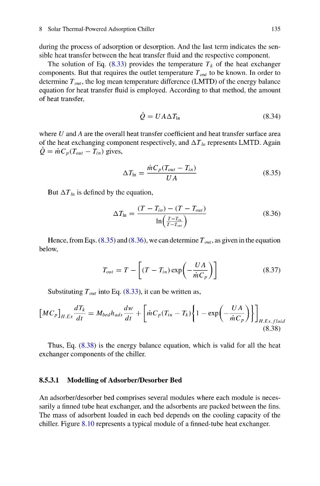
Hence, from Eqs. (8.35) and (8.36), we can determine T out , as given in the equation
below,
T out = T −
(T − T in ) exp
−
U A
˙
mC p
(8.37)
Substituting T out into Eq. (8.33), it can be written as,
MC p
H.E x
dT k
dt
= M bed h ads
dw
dt
+
˙
mC p (T in − T k )
1 − exp
−
U A
˙
mC p
H.E x. f luid
(8.38)
Thus, Eq. (8.38) is the energy balance equation, which is valid for all the heat
exchanger components of the chiller.
8.5.3.1 Modelling of Adsorber/Desorber Bed
An adsorber/desorber bed comprises several modules where each module is necessarily a finned tube heat exchanger, and the adsorbents are packed between the fins.
The mass of adsorbent loaded in each bed depends on the cooling capacity of the
chiller. Figure 8.10 represents a typical module of a finned-tube heat exchanger.
135
during the process of adsorption or desorption. And the last term indicates the sensible heat transfer between the heat transfer fluid and the respective component.
The solution of Eq. (8.33) provides the temperature T k of the heat exchanger
components. But that requires the outlet temperature T out to be known. In order to
determine T out , the log mean temperature difference (LMTD) of the energy balance
equation for heat transfer fluid is employed. According to that method, the amount
of heat transfer,
˙
Q = U AT ln
(8.34)
where U and A are the overall heat transfer coefficient and heat transfer surface area
of the heat exchanging component respectively, and T ln represents LMTD. Again
˙
Q = ˙
mC p (T out − T in ) gives,
T ln =
˙
mC p (T out − T in )
U A
(8.35)
But T ln is defined by the equation,
T ln =
(T − T in ) − (T − T out )
ln
T −T in
T −T out
(8.36)
Hence, from Eqs. (8.35) and (8.36), we can determine T out , as given in the equation
below,
T out = T −
(T − T in ) exp
−
U A
˙
mC p
(8.37)
Substituting T out into Eq. (8.33), it can be written as,
MC p
H.E x
dT k
dt
= M bed h ads
dw
dt
+
˙
mC p (T in − T k )
1 − exp
−
U A
˙
mC p
H.E x. f luid
(8.38)
Thus, Eq. (8.38) is the energy balance equation, which is valid for all the heat
exchanger components of the chiller.
8.5.3.1 Modelling of Adsorber/Desorber Bed
An adsorber/desorber bed comprises several modules where each module is necessarily a finned tube heat exchanger, and the adsorbents are packed between the fins.
The mass of adsorbent loaded in each bed depends on the cooling capacity of the
chiller. Figure 8.10 represents a typical module of a finned-tube heat exchanger.