

and R SYST ¼ 1 À F SYST gives R SYST ¼ 1 À 0:01 ¼ 0:99
(a) Therefore, the reliability of the booster pumps ¼ 0.99
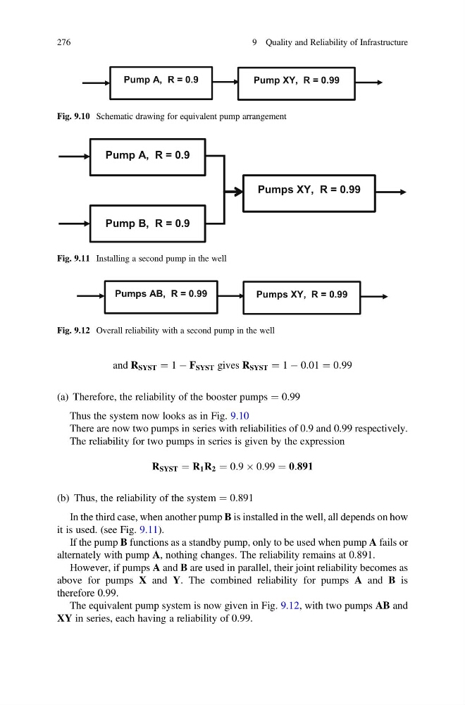
Thus the system now looks as in Fig. 9.10
There are now two pumps in series with reliabilities of 0.9 and 0.99 respectively.
The reliability for two pumps in series is given by the expression
R SYST ¼ R 1 R 2 ¼ 0:9 Â 0:99 ¼ 0:891
(b) Thus, the reliability of the system ¼ 0.891
In the third case, when another pump B is installed in the well, all depends on how
it is used. (see Fig. 9.11).
If the pump B functions as a standby pump, only to be used when pump A fails or
alternately with pump A, nothing changes. The reliability remains at 0.891.
However, if pumps A and B are used in parallel, their joint reliability becomes as
above for pumps X and Y. The combined reliability for pumps A and B is
therefore 0.99.
The equivalent pump system is now given in Fig. 9.12, with two pumps AB and
XY in series, each having a reliability of 0.99.
Pump A, R = 0.9
Pump XY, R = 0.99
Fig. 9.10 Schematic drawing for equivalent pump arrangement
Pump A, R = 0.9
Pumps XY, R = 0.99
Pump B, R = 0.9
Fig. 9.11 Installing a second pump in the well
Pumps AB, R = 0.99
Pumps XY, R = 0.99
Fig. 9.12 Overall reliability with a second pump in the well
276
9 Quality and Reliability of Infrastructure
(a) Therefore, the reliability of the booster pumps ¼ 0.99
Thus the system now looks as in Fig. 9.10
There are now two pumps in series with reliabilities of 0.9 and 0.99 respectively.
The reliability for two pumps in series is given by the expression
R SYST ¼ R 1 R 2 ¼ 0:9 Â 0:99 ¼ 0:891
(b) Thus, the reliability of the system ¼ 0.891
In the third case, when another pump B is installed in the well, all depends on how
it is used. (see Fig. 9.11).
If the pump B functions as a standby pump, only to be used when pump A fails or
alternately with pump A, nothing changes. The reliability remains at 0.891.
However, if pumps A and B are used in parallel, their joint reliability becomes as
above for pumps X and Y. The combined reliability for pumps A and B is
therefore 0.99.
The equivalent pump system is now given in Fig. 9.12, with two pumps AB and
XY in series, each having a reliability of 0.99.
Pump A, R = 0.9
Pump XY, R = 0.99
Fig. 9.10 Schematic drawing for equivalent pump arrangement
Pump A, R = 0.9
Pumps XY, R = 0.99
Pump B, R = 0.9
Fig. 9.11 Installing a second pump in the well
Pumps AB, R = 0.99
Pumps XY, R = 0.99
Fig. 9.12 Overall reliability with a second pump in the well
276
9 Quality and Reliability of Infrastructure