

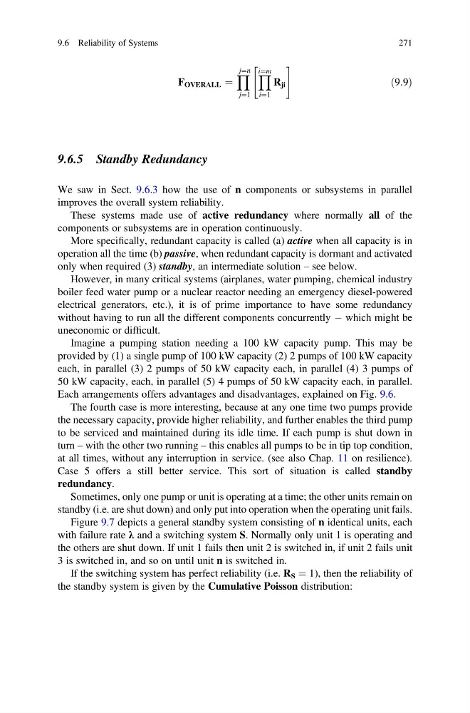
F OVERALL ¼
Y j¼n
j¼1
Y i¼m
i¼1
R ji
"
#
ð9:9Þ
9.6.5 Standby Redundancy
We saw in Sect. 9.6.3 how the use of n components or subsystems in parallel
improves the overall system reliability.
These systems made use of active redundancy where normally all of the
components or subsystems are in operation continuously.
More specifically, redundant capacity is called (a) active when all capacity is in
operation all the time (b) passive, when redundant capacity is dormant and activated
only when required (3) standby, an intermediate solution – see below.
However, in many critical systems (airplanes, water pumping, chemical industry
boiler feed water pump or a nuclear reactor needing an emergency diesel-powered
electrical generators, etc.), it is of prime importance to have some redundancy
without having to run all the different components concurrently À which might be
uneconomic or difficult.
Imagine a pumping station needing a 100 kW capacity pump. This may be
provided by (1) a single pump of 100 kW capacity (2) 2 pumps of 100 kW capacity
each, in parallel (3) 2 pumps of 50 kW capacity each, in parallel (4) 3 pumps of
50 kW capacity, each, in parallel (5) 4 pumps of 50 kW capacity each, in parallel.
Each arrangements offers advantages and disadvantages, explained on Fig. 9.6.
The fourth case is more interesting, because at any one time two pumps provide
the necessary capacity, provide higher reliability, and further enables the third pump
to be serviced and maintained during its idle time. If each pump is shut down in
turn – with the other two running – this enables all pumps to be in tip top condition,
at all times, without any interruption in service. (see also Chap. 11 on resilience).
Case 5 offers a still better service. This sort of situation is called standby
redundancy.
Sometimes, only one pump or unit is operating at a time; the other units remain on
standby (i.e. are shut down) and only put into operation when the operating unit fails.
Figure 9.7 depicts a general standby system consisting of n identical units, each
with failure rate λ and a switching system S. Normally only unit 1 is operating and
the others are shut down. If unit 1 fails then unit 2 is switched in, if unit 2 fails unit
3 is switched in, and so on until unit n is switched in.
If the switching system has perfect reliability (i.e. R S ¼ 1), then the reliability of
the standby system is given by the Cumulative Poisson distribution:
9.6 Reliability of Systems
271
Y j¼n
j¼1
Y i¼m
i¼1
R ji
"
#
ð9:9Þ
9.6.5 Standby Redundancy
We saw in Sect. 9.6.3 how the use of n components or subsystems in parallel
improves the overall system reliability.
These systems made use of active redundancy where normally all of the
components or subsystems are in operation continuously.
More specifically, redundant capacity is called (a) active when all capacity is in
operation all the time (b) passive, when redundant capacity is dormant and activated
only when required (3) standby, an intermediate solution – see below.
However, in many critical systems (airplanes, water pumping, chemical industry
boiler feed water pump or a nuclear reactor needing an emergency diesel-powered
electrical generators, etc.), it is of prime importance to have some redundancy
without having to run all the different components concurrently À which might be
uneconomic or difficult.
Imagine a pumping station needing a 100 kW capacity pump. This may be
provided by (1) a single pump of 100 kW capacity (2) 2 pumps of 100 kW capacity
each, in parallel (3) 2 pumps of 50 kW capacity each, in parallel (4) 3 pumps of
50 kW capacity, each, in parallel (5) 4 pumps of 50 kW capacity each, in parallel.
Each arrangements offers advantages and disadvantages, explained on Fig. 9.6.
The fourth case is more interesting, because at any one time two pumps provide
the necessary capacity, provide higher reliability, and further enables the third pump
to be serviced and maintained during its idle time. If each pump is shut down in
turn – with the other two running – this enables all pumps to be in tip top condition,
at all times, without any interruption in service. (see also Chap. 11 on resilience).
Case 5 offers a still better service. This sort of situation is called standby
redundancy.
Sometimes, only one pump or unit is operating at a time; the other units remain on
standby (i.e. are shut down) and only put into operation when the operating unit fails.
Figure 9.7 depicts a general standby system consisting of n identical units, each
with failure rate λ and a switching system S. Normally only unit 1 is operating and
the others are shut down. If unit 1 fails then unit 2 is switched in, if unit 2 fails unit
3 is switched in, and so on until unit n is switched in.
If the switching system has perfect reliability (i.e. R S ¼ 1), then the reliability of
the standby system is given by the Cumulative Poisson distribution:
9.6 Reliability of Systems
271