

4 Solar Cells: Optical and Recombination Losses
81
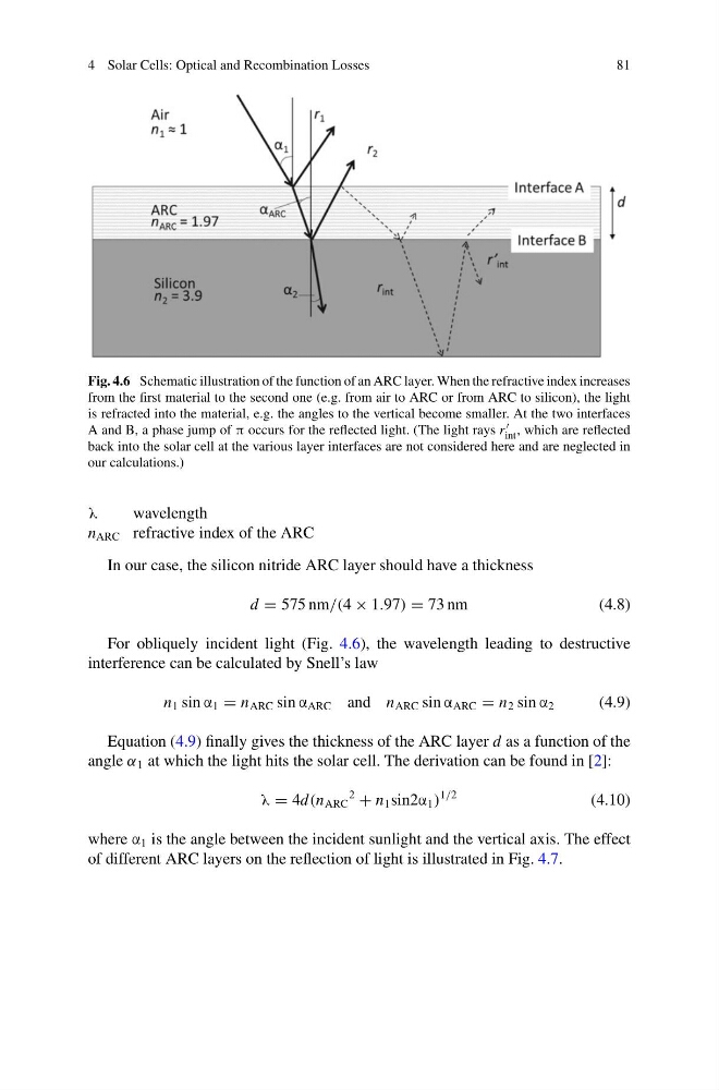
Fig. 4.6 Schematic illustration of the function of an ARC layer. When the refractive index increases
from the first material to the second one (e.g. from air to ARC or from ARC to silicon), the light
is refracted into the material, e.g. the angles to the vertical become smaller. At the two interfaces
A and B, a phase jump of π occurs for the reflected light. (The light rays r
int , which are reflected
back into the solar cell at the various layer interfaces are not considered here and are neglected in
our calculations.)
λ
wavelength
n ARC refractive index of the ARC
In our case, the silicon nitride ARC layer should have a thickness
d = 575 nm/(4 × 1.97) = 73 nm
(4.8)
For obliquely incident light (Fig. 4.6), the wavelength leading to destructive
interference can be calculated by Snell’s law
n 1 sin α 1 = n ARC sin α ARC and n ARC sin α ARC = n 2 sin α 2
(4.9)
Equation (4.9) finally gives the thickness of the ARC layer d as a function of the
angle α 1 at which the light hits the solar cell. The derivation can be found in [2]:
λ = 4d(n ARC
2
+ n 1 sin2α 1 )
1/2
(4.10)
where α 1 is the angle between the incident sunlight and the vertical axis. The effect
of different ARC layers on the reflection of light is illustrated in Fig. 4.7.
81
Fig. 4.6 Schematic illustration of the function of an ARC layer. When the refractive index increases
from the first material to the second one (e.g. from air to ARC or from ARC to silicon), the light
is refracted into the material, e.g. the angles to the vertical become smaller. At the two interfaces
A and B, a phase jump of π occurs for the reflected light. (The light rays r
int , which are reflected
back into the solar cell at the various layer interfaces are not considered here and are neglected in
our calculations.)
λ
wavelength
n ARC refractive index of the ARC
In our case, the silicon nitride ARC layer should have a thickness
d = 575 nm/(4 × 1.97) = 73 nm
(4.8)
For obliquely incident light (Fig. 4.6), the wavelength leading to destructive
interference can be calculated by Snell’s law
n 1 sin α 1 = n ARC sin α ARC and n ARC sin α ARC = n 2 sin α 2
(4.9)
Equation (4.9) finally gives the thickness of the ARC layer d as a function of the
angle α 1 at which the light hits the solar cell. The derivation can be found in [2]:
λ = 4d(n ARC
2
+ n 1 sin2α 1 )
1/2
(4.10)
where α 1 is the angle between the incident sunlight and the vertical axis. The effect
of different ARC layers on the reflection of light is illustrated in Fig. 4.7.