

10 Module Deployment and Energy Rating
265
modules connected in series in the same string will be affected, as if all the modules
were of “bad” quality.
If the previous two loss mechanisms depend only on the quality of the modules
and should be minimal with good quality products, the Ohmic losses of the cables
connecting the modules to the inverter is a physical phenomenon that always occurs.
It is well known from basic physics that conductors dissipate heat when current flows
through them, due to the so-called “Joule effect”
P = R I
2
(10.9)
where P is the power loss, R is the resistance of the conductor (depending on the
material of the conductor, its length, its section and its temperature) and I is the current
flowing through the conductor. The power loss is larger at higher temperatures and
for longer cables, but it is mitigated by a larger size of the cables. As an example,
if the distance from the string and the inverter is 15 m (accounting for 30 m of total
cable length), copper cables connecting commercial modules (current: ~8 A; cable
section: 6 mm
2 ) show Ohmic losses of 5–6 W in the temperature range 30–60 °C.
So far, as to the power losses from the module to the inverter (i.e. on the “DC
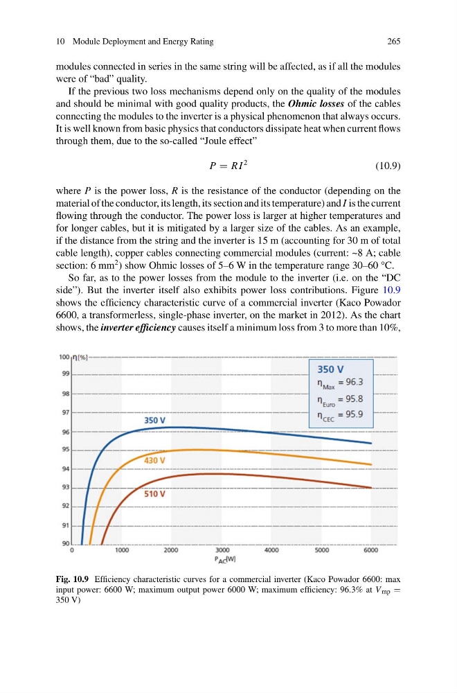
side”). But the inverter itself also exhibits power loss contributions. Figure 10.9
shows the efficiency characteristic curve of a commercial inverter (Kaco Powador
6600, a transformerless, single-phase inverter, on the market in 2012). As the chart
shows, the inverter efficiency causes itself a minimum loss from 3 to more than 10%,
Fig. 10.9 Efficiency characteristic curves for a commercial inverter (Kaco Powador 6600: max
input power: 6600 W; maximum output power 6000 W; maximum efficiency: 96.3% at V mp =
350 V)
265
modules connected in series in the same string will be affected, as if all the modules
were of “bad” quality.
If the previous two loss mechanisms depend only on the quality of the modules
and should be minimal with good quality products, the Ohmic losses of the cables
connecting the modules to the inverter is a physical phenomenon that always occurs.
It is well known from basic physics that conductors dissipate heat when current flows
through them, due to the so-called “Joule effect”
P = R I
2
(10.9)
where P is the power loss, R is the resistance of the conductor (depending on the
material of the conductor, its length, its section and its temperature) and I is the current
flowing through the conductor. The power loss is larger at higher temperatures and
for longer cables, but it is mitigated by a larger size of the cables. As an example,
if the distance from the string and the inverter is 15 m (accounting for 30 m of total
cable length), copper cables connecting commercial modules (current: ~8 A; cable
section: 6 mm
2 ) show Ohmic losses of 5–6 W in the temperature range 30–60 °C.
So far, as to the power losses from the module to the inverter (i.e. on the “DC
side”). But the inverter itself also exhibits power loss contributions. Figure 10.9
shows the efficiency characteristic curve of a commercial inverter (Kaco Powador
6600, a transformerless, single-phase inverter, on the market in 2012). As the chart
shows, the inverter efficiency causes itself a minimum loss from 3 to more than 10%,
Fig. 10.9 Efficiency characteristic curves for a commercial inverter (Kaco Powador 6600: max
input power: 6600 W; maximum output power 6000 W; maximum efficiency: 96.3% at V mp =
350 V)