

7 Crystalline Silicon Solar Cells: Heterojunction Cells
173
the valence band help in obtaining a more effective separation of charge carriers.
Since holes can flow freely to the left-side contact, but electrons do not flow in that
direction, an ideal contact—without any recombination at the electrode surface, is
formed (selective contacts or passivated contacts).
However, the peak must not be too high, otherwise it constitutes a blockade and
the holes cannot tunnel through. Conversely, if the peak is too small, cell efficiency
and the fill factor are reduced [7]. Later in Sect. 7.2.3, we will also look at the back
side of the HJT cell and see then that there is a peak at the back side, as well, through
which the electrons can tunnel through.
Thanks to the fact that almost no electrons flow through the (p) amorphous silicon
layer (and similarly on the back side, no holes flow through the a-Si(n) amorphous
silicon layer), recombination losses are avoided. The contacts created in this manner are passivated contacts. They are selective and not Ohmic. They let either only
the holes pass through or else only the electrons pass through. [8] In addition, these
selective barriers are unidirectional: The charge carriers, once they tunnel through the
barrier, cannot return. And finally, they are not Ohmic contacts and reduce recombination losses. This has an impact on the equivalent circuit diagram. In the equivalent
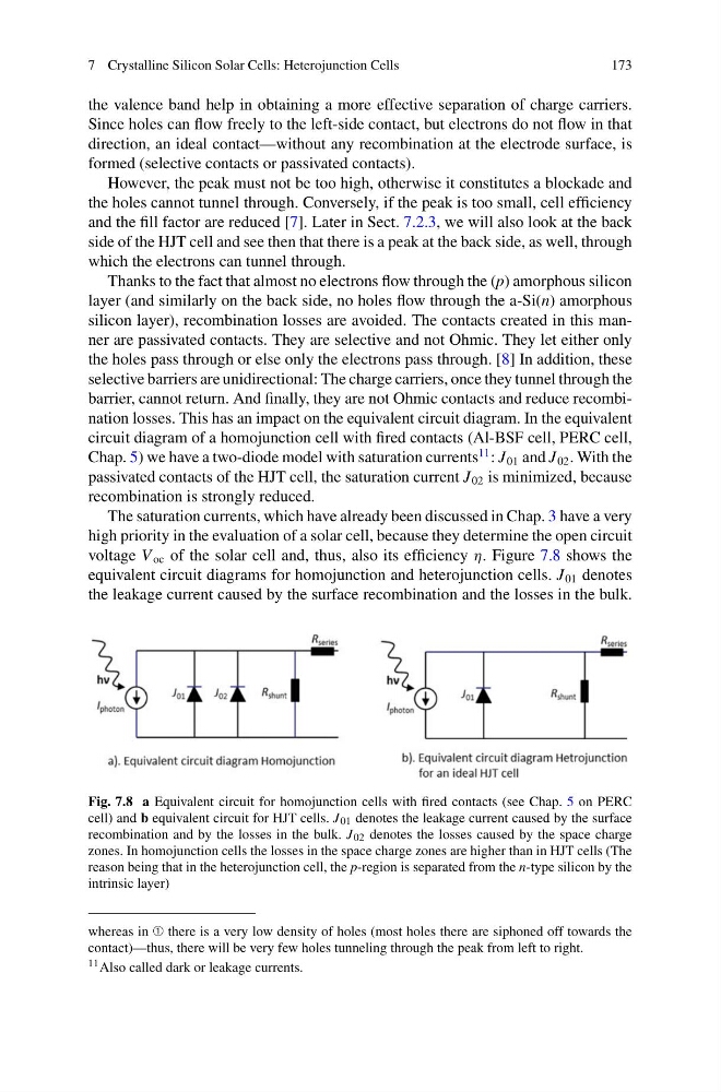
circuit diagram of a homojunction cell with fired contacts (Al-BSF cell, PERC cell,
Chap. 5) we have a two-diode model with saturation currents
11 : J 01 and J 02 . With the
passivated contacts of the HJT cell, the saturation current J 02 is minimized, because
recombination is strongly reduced.
The saturation currents, which have already been discussed in Chap. 3 have a very
high priority in the evaluation of a solar cell, because they determine the open circuit
voltage V oc of the solar cell and, thus, also its efficiency η. Figure 7.8 shows the
equivalent circuit diagrams for homojunction and heterojunction cells. J 01 denotes
the leakage current caused by the surface recombination and the losses in the bulk.
Fig. 7.8 a Equivalent circuit for homojunction cells with fired contacts (see Chap. 5 on PERC
cell) and b equivalent circuit for HJT cells. J 01 denotes the leakage current caused by the surface
recombination and by the losses in the bulk. J 02 denotes the losses caused by the space charge
zones. In homojunction cells the losses in the space charge zones are higher than in HJT cells (The
reason being that in the heterojunction cell, the p-region is separated from the n-type silicon by the
intrinsic layer)
whereas in ➀ there is a very low density of holes (most holes there are siphoned off towards the
contact)—thus, there will be very few holes tunneling through the peak from left to right.
11 Also called dark or leakage currents.
173
the valence band help in obtaining a more effective separation of charge carriers.
Since holes can flow freely to the left-side contact, but electrons do not flow in that
direction, an ideal contact—without any recombination at the electrode surface, is
formed (selective contacts or passivated contacts).
However, the peak must not be too high, otherwise it constitutes a blockade and
the holes cannot tunnel through. Conversely, if the peak is too small, cell efficiency
and the fill factor are reduced [7]. Later in Sect. 7.2.3, we will also look at the back
side of the HJT cell and see then that there is a peak at the back side, as well, through
which the electrons can tunnel through.
Thanks to the fact that almost no electrons flow through the (p) amorphous silicon
layer (and similarly on the back side, no holes flow through the a-Si(n) amorphous
silicon layer), recombination losses are avoided. The contacts created in this manner are passivated contacts. They are selective and not Ohmic. They let either only
the holes pass through or else only the electrons pass through. [8] In addition, these
selective barriers are unidirectional: The charge carriers, once they tunnel through the
barrier, cannot return. And finally, they are not Ohmic contacts and reduce recombination losses. This has an impact on the equivalent circuit diagram. In the equivalent
circuit diagram of a homojunction cell with fired contacts (Al-BSF cell, PERC cell,
Chap. 5) we have a two-diode model with saturation currents
11 : J 01 and J 02 . With the
passivated contacts of the HJT cell, the saturation current J 02 is minimized, because
recombination is strongly reduced.
The saturation currents, which have already been discussed in Chap. 3 have a very
high priority in the evaluation of a solar cell, because they determine the open circuit
voltage V oc of the solar cell and, thus, also its efficiency η. Figure 7.8 shows the
equivalent circuit diagrams for homojunction and heterojunction cells. J 01 denotes
the leakage current caused by the surface recombination and the losses in the bulk.
Fig. 7.8 a Equivalent circuit for homojunction cells with fired contacts (see Chap. 5 on PERC
cell) and b equivalent circuit for HJT cells. J 01 denotes the leakage current caused by the surface
recombination and by the losses in the bulk. J 02 denotes the losses caused by the space charge
zones. In homojunction cells the losses in the space charge zones are higher than in HJT cells (The
reason being that in the heterojunction cell, the p-region is separated from the n-type silicon by the
intrinsic layer)
whereas in ➀ there is a very low density of holes (most holes there are siphoned off towards the
contact)—thus, there will be very few holes tunneling through the peak from left to right.
11 Also called dark or leakage currents.