

166
S. Leu and D. Sontag
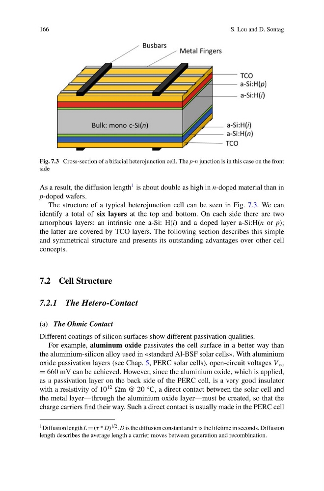
Fig. 7.3 Cross-section of a bifacial heterojunction cell. The p-n junction is in this case on the front
side
As a result, the diffusion length
1 is about double as high in n-doped material than in
p-doped wafers.
The structure of a typical heterojunction cell can be seen in Fig. 7.3. We can
identify a total of six layers at the top and bottom. On each side there are two
amorphous layers: an intrinsic one a-Si: H(i) and a doped layer a-Si:H(n or p);
the latter are covered by TCO layers. The following section describes this simple
and symmetrical structure and presents its outstanding advantages over other cell
concepts.
7.2 Cell Structure
7.2.1 The Hetero-Contact
(a) The Ohmic Contact
Different coatings of silicon surfaces show different passivation qualities.
For example, aluminum oxide passivates the cell surface in a better way than
the aluminium-silicon alloy used in «standard Al-BSF solar cells». With aluminium
oxide passivation layers (see Chap. 5, PERC solar cells), open-circuit voltages V oc
= 660 mV can be achieved. However, since the aluminium oxide, which is applied,
as a passivation layer on the back side of the PERC cell, is a very good insulator
with a resistivity of 10
12
m @ 20 °C, a direct contact between the solar cell and
the metal layer—through the aluminium oxide layer—must be created, so that the
charge carriers find their way. Such a direct contact is usually made in the PERC cell
1 Diffusion length L = (τ * D) 1/2 . D is the diffusion constant and τ is the lifetime in seconds. Diffusion
length describes the average length a carrier moves between generation and recombination.
S. Leu and D. Sontag
Fig. 7.3 Cross-section of a bifacial heterojunction cell. The p-n junction is in this case on the front
side
As a result, the diffusion length
1 is about double as high in n-doped material than in
p-doped wafers.
The structure of a typical heterojunction cell can be seen in Fig. 7.3. We can
identify a total of six layers at the top and bottom. On each side there are two
amorphous layers: an intrinsic one a-Si: H(i) and a doped layer a-Si:H(n or p);
the latter are covered by TCO layers. The following section describes this simple
and symmetrical structure and presents its outstanding advantages over other cell
concepts.
7.2 Cell Structure
7.2.1 The Hetero-Contact
(a) The Ohmic Contact
Different coatings of silicon surfaces show different passivation qualities.
For example, aluminum oxide passivates the cell surface in a better way than
the aluminium-silicon alloy used in «standard Al-BSF solar cells». With aluminium
oxide passivation layers (see Chap. 5, PERC solar cells), open-circuit voltages V oc
= 660 mV can be achieved. However, since the aluminium oxide, which is applied,
as a passivation layer on the back side of the PERC cell, is a very good insulator
with a resistivity of 10
12
m @ 20 °C, a direct contact between the solar cell and
the metal layer—through the aluminium oxide layer—must be created, so that the
charge carriers find their way. Such a direct contact is usually made in the PERC cell
1 Diffusion length L = (τ * D) 1/2 . D is the diffusion constant and τ is the lifetime in seconds. Diffusion
length describes the average length a carrier moves between generation and recombination.