

emission source with the average output power of 3–10 mW. The second OEO
feature in the microwave range is utilization of the single-mode low-dispersion fiber
light guide as the retarding fiber-optical structure. For photodetection of the optical
emission, the modern ultra-wideband (with bandwidth of 12–15 GHz) photodiode is
used in OEO. The microwave amplifier with power supply regulation and the
bandwidth about 1 GHz and the RF microwave filter on the base of the dielectric
cavity with bandwidth about 2 MHz provide amplification and selectivity of microwave oscillations in OEO. The natural frequency of the RF filter is about 8.2 GHz.
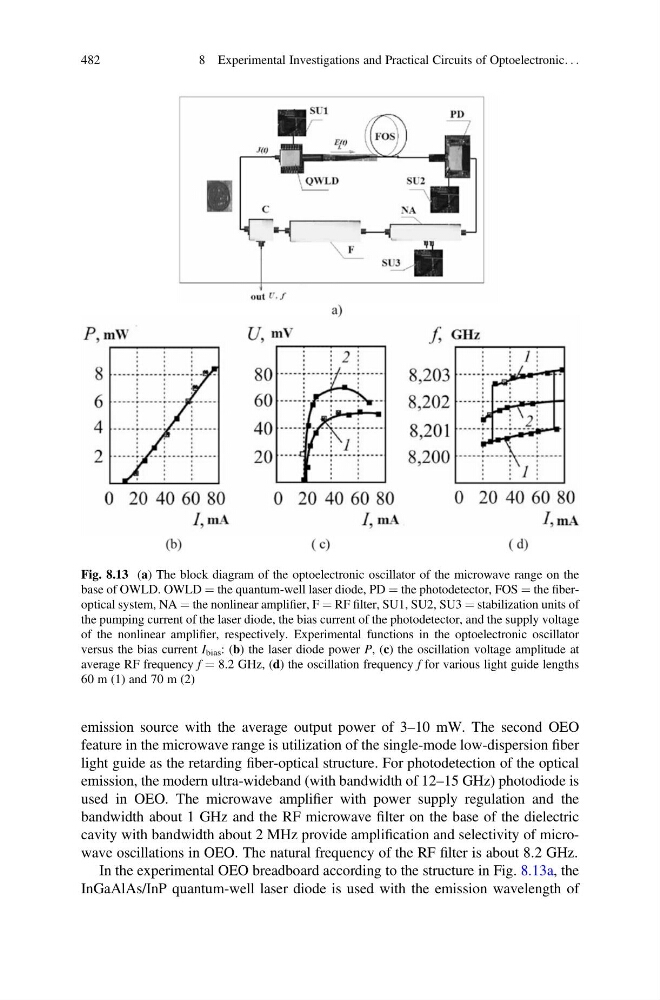
In the experimental OEO breadboard according to the structure in Fig. 8.13a, the
InGaAlAs/InP quantum-well laser diode is used with the emission wavelength of
Fig. 8.13 (a) The block diagram of the optoelectronic oscillator of the microwave range on the
base of OWLD. OWLD ¼ the quantum-well laser diode, PD ¼ the photodetector, FOS ¼ the fiberoptical system, NA ¼ the nonlinear amplifier, F ¼ RF filter, SU1, SU2, SU3 ¼ stabilization units of
the pumping current of the laser diode, the bias current of the photodetector, and the supply voltage
of the nonlinear amplifier, respectively. Experimental functions in the optoelectronic oscillator
versus the bias current I bias : (b) the laser diode power P, (c) the oscillation voltage amplitude at
average RF frequency f ¼ 8.2 GHz, (d) the oscillation frequency f for various light guide lengths
60 m (1) and 70 m (2)
482
8 Experimental Investigations and Practical Circuits of Optoelectronic. . .
feature in the microwave range is utilization of the single-mode low-dispersion fiber
light guide as the retarding fiber-optical structure. For photodetection of the optical
emission, the modern ultra-wideband (with bandwidth of 12–15 GHz) photodiode is
used in OEO. The microwave amplifier with power supply regulation and the
bandwidth about 1 GHz and the RF microwave filter on the base of the dielectric
cavity with bandwidth about 2 MHz provide amplification and selectivity of microwave oscillations in OEO. The natural frequency of the RF filter is about 8.2 GHz.
In the experimental OEO breadboard according to the structure in Fig. 8.13a, the
InGaAlAs/InP quantum-well laser diode is used with the emission wavelength of
Fig. 8.13 (a) The block diagram of the optoelectronic oscillator of the microwave range on the
base of OWLD. OWLD ¼ the quantum-well laser diode, PD ¼ the photodetector, FOS ¼ the fiberoptical system, NA ¼ the nonlinear amplifier, F ¼ RF filter, SU1, SU2, SU3 ¼ stabilization units of
the pumping current of the laser diode, the bias current of the photodetector, and the supply voltage
of the nonlinear amplifier, respectively. Experimental functions in the optoelectronic oscillator
versus the bias current I bias : (b) the laser diode power P, (c) the oscillation voltage amplitude at
average RF frequency f ¼ 8.2 GHz, (d) the oscillation frequency f for various light guide lengths
60 m (1) and 70 m (2)
482
8 Experimental Investigations and Practical Circuits of Optoelectronic. . .