

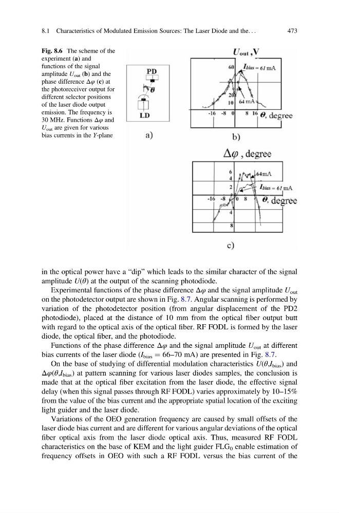
in the optical power have a “dip” which leads to the similar character of the signal
amplitude U(θ) at the output of the scanning photodiode.
Experimental functions of the phase difference Δφ and the signal amplitude U out
on the photodetector output are shown in Fig. 8.7. Angular scanning is performed by
variation of the photodetector position (from angular displacement of the PD2
photodiode), placed at the distance of 10 mm from the optical fiber output butt
with regard to the optical axis of the optical fiber. RF FODL is formed by the laser
diode, the optical fiber, and the photodiode.
Functions of the phase difference Δφ and the signal amplitude U out at different
bias currents of the laser diode (I bias ¼ 66–70 mA) are presented in Fig. 8.7.
On the base of studying of differential modulation characteristics U(θ,I bias ) and
Δφ(θ,I bias ) at pattern scanning for various laser diodes samples, the conclusion is
made that at the optical fiber excitation from the laser diode, the effective signal
delay (when this signal passes through RF FODL) varies approximately by 10–15%
from the value of the bias current and the appropriate spatial location of the exciting
light guider and the laser diode.
Variations of the OEO generation frequency are caused by small offsets of the
laser diode bias current and are different for various angular deviations of the optical
fiber optical axis from the laser diode optical axis. Thus, measured RF FODL
characteristics on the base of KEM and the light guider FLG 0 enable estimation of
frequency offsets in OEO with such a RF FODL versus the bias current of the
Fig. 8.6 The scheme of the
experiment (a) and
functions of the signal
amplitude U out (b) and the
phase difference Δφ (c) at
the photoreceiver output for
different selector positions
of the laser diode output
emission. The frequency is
30 MHz. Functions Δφ and
U out are given for various
bias currents in the Y-plane
8.1 Characteristics of Modulated Emission Sources: The Laser Diode and the. . .
473
amplitude U(θ) at the output of the scanning photodiode.
Experimental functions of the phase difference Δφ and the signal amplitude U out
on the photodetector output are shown in Fig. 8.7. Angular scanning is performed by
variation of the photodetector position (from angular displacement of the PD2
photodiode), placed at the distance of 10 mm from the optical fiber output butt
with regard to the optical axis of the optical fiber. RF FODL is formed by the laser
diode, the optical fiber, and the photodiode.
Functions of the phase difference Δφ and the signal amplitude U out at different
bias currents of the laser diode (I bias ¼ 66–70 mA) are presented in Fig. 8.7.
On the base of studying of differential modulation characteristics U(θ,I bias ) and
Δφ(θ,I bias ) at pattern scanning for various laser diodes samples, the conclusion is
made that at the optical fiber excitation from the laser diode, the effective signal
delay (when this signal passes through RF FODL) varies approximately by 10–15%
from the value of the bias current and the appropriate spatial location of the exciting
light guider and the laser diode.
Variations of the OEO generation frequency are caused by small offsets of the
laser diode bias current and are different for various angular deviations of the optical
fiber optical axis from the laser diode optical axis. Thus, measured RF FODL
characteristics on the base of KEM and the light guider FLG 0 enable estimation of
frequency offsets in OEO with such a RF FODL versus the bias current of the
Fig. 8.6 The scheme of the
experiment (a) and
functions of the signal
amplitude U out (b) and the
phase difference Δφ (c) at
the photoreceiver output for
different selector positions
of the laser diode output
emission. The frequency is
30 MHz. Functions Δφ and
U out are given for various
bias currents in the Y-plane
8.1 Characteristics of Modulated Emission Sources: The Laser Diode and the. . .
473