

functions of the signal frequency and amplitude are measured in OEO with RF
FODL (based on the single fiber-optical light guider) at variation of the bias current
of the emission source. These functions are measured for two different RF FODLs
on the base of single light guiders with lengths 20 and 300 m.
Figure 8.6 shows experimental functions of amplitude and phase difference of
signal modulation at scanning over the “aperture” of the laser diode emission pattern
in two different mutually orthogonal X (in the p-n junction plane) and Y planes.
The signal amplitude U at the output of the scanning photodetector and the phase
difference Δφ(θ) of signals at input of the laser diode modulator (and measured at the
photodetector output) were measured. Measurements of the phase difference are
performed with the help of the phase-meter FK-2-12. Figure 8.6a shows the functions of the modulated signal amplitude at the photodetector output U(θ), where θ is
the angle between the laser diode optical axis and a normal to the photodetector
light-sensitive area. At that, the sine signal of small amplitude (less than 0.05 V) and
at f ¼ 30 MHz frequency was applied to the laser diode input.
An analysis of functions U(θ) and Δφ(θ) at different bias currents shows that the
emission pattern for the laser diode of 32DL-03 type has a complicate character and
complicate non-monotonic dependence upon angular displacements θ at various bias
(pumping) currents I bias . At growth of the bias current I bias , the temperature increase
occurs in the laser diode optical resonator, and the refraction index in the active area
varies. This leads to appearance of longitudinal spatial modes of emission of the
higher order in the laser diode optical emission. At that, patterns of output emission
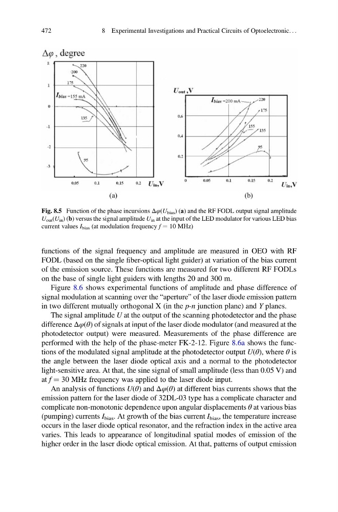
Fig. 8.5 Function of the phase incursions Δφ(U bias ) (а) and the RF FODL output signal amplitude
U out (U in ) (b) versus the signal amplitude U in at the input of the LED modulator for various LED bias
current values I bias (at modulation frequency f ¼ 10 MHz)
472
8 Experimental Investigations and Practical Circuits of Optoelectronic. . .
FODL (based on the single fiber-optical light guider) at variation of the bias current
of the emission source. These functions are measured for two different RF FODLs
on the base of single light guiders with lengths 20 and 300 m.
Figure 8.6 shows experimental functions of amplitude and phase difference of
signal modulation at scanning over the “aperture” of the laser diode emission pattern
in two different mutually orthogonal X (in the p-n junction plane) and Y planes.
The signal amplitude U at the output of the scanning photodetector and the phase
difference Δφ(θ) of signals at input of the laser diode modulator (and measured at the
photodetector output) were measured. Measurements of the phase difference are
performed with the help of the phase-meter FK-2-12. Figure 8.6a shows the functions of the modulated signal amplitude at the photodetector output U(θ), where θ is
the angle between the laser diode optical axis and a normal to the photodetector
light-sensitive area. At that, the sine signal of small amplitude (less than 0.05 V) and
at f ¼ 30 MHz frequency was applied to the laser diode input.
An analysis of functions U(θ) and Δφ(θ) at different bias currents shows that the
emission pattern for the laser diode of 32DL-03 type has a complicate character and
complicate non-monotonic dependence upon angular displacements θ at various bias
(pumping) currents I bias . At growth of the bias current I bias , the temperature increase
occurs in the laser diode optical resonator, and the refraction index in the active area
varies. This leads to appearance of longitudinal spatial modes of emission of the
higher order in the laser diode optical emission. At that, patterns of output emission
Fig. 8.5 Function of the phase incursions Δφ(U bias ) (а) and the RF FODL output signal amplitude
U out (U in ) (b) versus the signal amplitude U in at the input of the LED modulator for various LED bias
current values I bias (at modulation frequency f ¼ 10 MHz)
472
8 Experimental Investigations and Practical Circuits of Optoelectronic. . .