

electrons begin to perform oscillating movements, and as a result, the function of the
system amplification coefficient versus the optical frequency has the sharply
expressed resonance peaks.
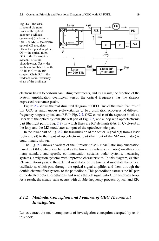
Figure 2.2 shows the real structural diagram of OEO. One of the main features of
this OEO is simultaneous self-excitation of two oscillation processes of different
frequency ranges: optical and RF. In Fig. 2.2, OEO consists of the separate blocks: a
laser with the optical system (the left part of Fig. 2.2) and a loop with optoelectronic
part (the right part in Fig. 2.2), in which there are RF elements (NA, F, C) closed in
the loop and the MZ modulator at input of the optoelectronic part.
In the lower part of Fig. 2.2, the transmission of the optical signal E(t) from a laser
(optical part) to the input of optoelectronic part (the input of the MZ modulator) is
conditionally shown.
The Fig. 2.3 shows a variant of the ultralow-noise RF oscillator implementation
based on OEO, which can be used as the low-noise reference (master) oscillator for
many standard and specific communication systems, radar systems, measuring
systems, navigation systems with improved characteristics. In this diagram, excited
RF oscillations pass to the external modulator of the laser and modulate the optical
oscillations, which pass through the optical signal amplifier and then, through the
double-channel fiber system, to the photodiode. This photodiode extracts the RF part
of modulated optical oscillations and sends the RF signal into OEO feedback loop.
As a result, the steady-state occurs with double-frequency process: optical and RF.
2.1.2 Methodic Conception and Features of OEO Theoretical
Investigation
Let us extract the main components of investigation conception accepted by us in
this book.
Fig. 2.2 The OEO
structural diagram:
Laser ¼ the optical
quantum oscillator
(generator) (the laser or
QWLD), MZ ¼ the electrooptical MZ modulator,
OA ¼ the optical amplifier,
OF ¼ the optical filter,
FOS ¼ the fiber-optical
system, PD ¼ the
photodetector, NA ¼ the
nonlinear amplifier, F ¼ the
RF filter, C ¼ the RF
coupler, Chain RF ¼ the
feedback radio-frequency
chain of the oscillator
2.1 Operation Principle and Functional Diagram of OEO with RF FODL
19
system amplification coefficient versus the optical frequency has the sharply
expressed resonance peaks.
Figure 2.2 shows the real structural diagram of OEO. One of the main features of
this OEO is simultaneous self-excitation of two oscillation processes of different
frequency ranges: optical and RF. In Fig. 2.2, OEO consists of the separate blocks: a
laser with the optical system (the left part of Fig. 2.2) and a loop with optoelectronic
part (the right part in Fig. 2.2), in which there are RF elements (NA, F, C) closed in
the loop and the MZ modulator at input of the optoelectronic part.
In the lower part of Fig. 2.2, the transmission of the optical signal E(t) from a laser
(optical part) to the input of optoelectronic part (the input of the MZ modulator) is
conditionally shown.
The Fig. 2.3 shows a variant of the ultralow-noise RF oscillator implementation
based on OEO, which can be used as the low-noise reference (master) oscillator for
many standard and specific communication systems, radar systems, measuring
systems, navigation systems with improved characteristics. In this diagram, excited
RF oscillations pass to the external modulator of the laser and modulate the optical
oscillations, which pass through the optical signal amplifier and then, through the
double-channel fiber system, to the photodiode. This photodiode extracts the RF part
of modulated optical oscillations and sends the RF signal into OEO feedback loop.
As a result, the steady-state occurs with double-frequency process: optical and RF.
2.1.2 Methodic Conception and Features of OEO Theoretical
Investigation
Let us extract the main components of investigation conception accepted by us in
this book.
Fig. 2.2 The OEO
structural diagram:
Laser ¼ the optical
quantum oscillator
(generator) (the laser or
QWLD), MZ ¼ the electrooptical MZ modulator,
OA ¼ the optical amplifier,
OF ¼ the optical filter,
FOS ¼ the fiber-optical
system, PD ¼ the
photodetector, NA ¼ the
nonlinear amplifier, F ¼ the
RF filter, C ¼ the RF
coupler, Chain RF ¼ the
feedback radio-frequency
chain of the oscillator
2.1 Operation Principle and Functional Diagram of OEO with RF FODL
19