

the light source, which are mounted in the mutual case with an active part of OEO
with RF FODL.
The experimental sample of OEO with RF FODL in the frequency range
30–40 MHz is developed on the base of the specially created transmitting unit
containing of laser diodes of various types (ILPN-204 or 32DL103) on the base of
the double hetero-structure with the emission wavelength of 0.85 μm.
The specially developed our receiving unit includes the photodiode LPD-2, the
wideband multistage amplifier with the total gain (in AC current) of 10
2
–10
3 , and the
matched (with this amplifier) temperature-controlled tuned circuit: the RF filter
(RFF) tuned on the frequency 30–40 MHz. This RFF bandwidth is 1–2 MHz. The
large gain of an amplifier gives a possibility to investigate the OEO frequency
responses at small general magnitudes of RF FODL transfer functions (much less
than 1).
The tuned circuit in OEO is made on the base of KSO capacitors and typical
inductors wounded on the ceramic cylinder. For matching and ensure of the small
effect of external electric circuits (for example, measuring devices), an oscillator
(Osc) contains of the decoupling amplifying stage made on the base of a field-effect
transistor.
Figure 8.3 shows the overall views of laser diodes ILPN-204 (a), 32DL-103 (b),
and the external view of the laser diode board with an electronic modulator (c). Also
Fig. 8.3 shows the laser diode SLT (the emission power is 10–25 mW, the emission
spectral line width is 10 MHz, the wavelength is 1.55 μm) (d), the laser diode Dilas
(the emission power is 10–15 mW, the wavelength is 1.3 μm, the RF modulation is
12GHz) (e), the photodiode Dilas (RF reception is 12 GHz) (f), the photodiode FRM
(RF reception is 15GHz) (g).
During experimental researches, we measured the watt–ampere characteristic
(Fig. 8.4) of the LED and the LD with the help of an optical tester OT-6.
Figure 8.4c shows experimental characteristics of W-A curves Р out (I bias ) for LD
samples of 32D-103 and ILPN-204 types, while Fig. 8.4b presents W-A curves for
them of the light-emitting diode included into the quantum-electronic unit QEM-34.
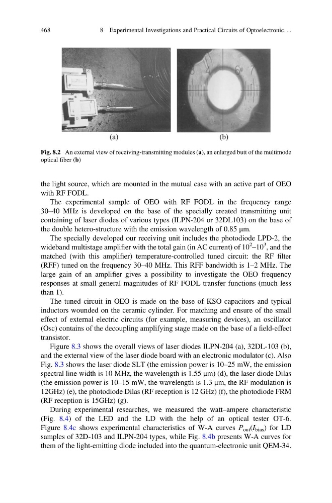
Fig. 8.2 An external view of receiving-transmitting modules (а), an enlarged butt of the multimode
optical fiber (b)
468
8 Experimental Investigations and Practical Circuits of Optoelectronic. . .
with RF FODL.
The experimental sample of OEO with RF FODL in the frequency range
30–40 MHz is developed on the base of the specially created transmitting unit
containing of laser diodes of various types (ILPN-204 or 32DL103) on the base of
the double hetero-structure with the emission wavelength of 0.85 μm.
The specially developed our receiving unit includes the photodiode LPD-2, the
wideband multistage amplifier with the total gain (in AC current) of 10
2
–10
3 , and the
matched (with this amplifier) temperature-controlled tuned circuit: the RF filter
(RFF) tuned on the frequency 30–40 MHz. This RFF bandwidth is 1–2 MHz. The
large gain of an amplifier gives a possibility to investigate the OEO frequency
responses at small general magnitudes of RF FODL transfer functions (much less
than 1).
The tuned circuit in OEO is made on the base of KSO capacitors and typical
inductors wounded on the ceramic cylinder. For matching and ensure of the small
effect of external electric circuits (for example, measuring devices), an oscillator
(Osc) contains of the decoupling amplifying stage made on the base of a field-effect
transistor.
Figure 8.3 shows the overall views of laser diodes ILPN-204 (a), 32DL-103 (b),
and the external view of the laser diode board with an electronic modulator (c). Also
Fig. 8.3 shows the laser diode SLT (the emission power is 10–25 mW, the emission
spectral line width is 10 MHz, the wavelength is 1.55 μm) (d), the laser diode Dilas
(the emission power is 10–15 mW, the wavelength is 1.3 μm, the RF modulation is
12GHz) (e), the photodiode Dilas (RF reception is 12 GHz) (f), the photodiode FRM
(RF reception is 15GHz) (g).
During experimental researches, we measured the watt–ampere characteristic
(Fig. 8.4) of the LED and the LD with the help of an optical tester OT-6.
Figure 8.4c shows experimental characteristics of W-A curves Р out (I bias ) for LD
samples of 32D-103 and ILPN-204 types, while Fig. 8.4b presents W-A curves for
them of the light-emitting diode included into the quantum-electronic unit QEM-34.
Fig. 8.2 An external view of receiving-transmitting modules (а), an enlarged butt of the multimode
optical fiber (b)
468
8 Experimental Investigations and Practical Circuits of Optoelectronic. . .