

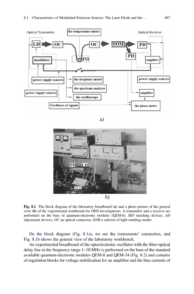
On the block diagram (Fig. 8.1a), we see the instruments’ connection, and
Fig. 8.1b shows the general view of the laboratory workbench.
An experimental breadboard of the optoelectronic oscillator with the fiber-optical
delay line in the frequency range 1–10 MHz is performed on the base of the standard
available quantum-electronic modules QEM-8 and QEM-34 (Fig. 8.2) and contains
of regulation blocks for voltage stabilization for an amplifier and the bias currents of
Fig. 8.1 The block diagram of the laboratory breadboard (а) and a photo picture of the general
view (b) of the experimental workbench for OEO investigations. A transmitter and a receiver are
performed on the base of quantum-electronic modules (QEM-8). MD matching devices, AD
adjustment devices, OC an optical connector, SOM a selector of light-emitting modes
8.1 Characteristics of Modulated Emission Sources: The Laser Diode and the. . .
467
Fig. 8.1b shows the general view of the laboratory workbench.
An experimental breadboard of the optoelectronic oscillator with the fiber-optical
delay line in the frequency range 1–10 MHz is performed on the base of the standard
available quantum-electronic modules QEM-8 and QEM-34 (Fig. 8.2) and contains
of regulation blocks for voltage stabilization for an amplifier and the bias currents of
Fig. 8.1 The block diagram of the laboratory breadboard (а) and a photo picture of the general
view (b) of the experimental workbench for OEO investigations. A transmitter and a receiver are
performed on the base of quantum-electronic modules (QEM-8). MD matching devices, AD
adjustment devices, OC an optical connector, SOM a selector of light-emitting modes
8.1 Characteristics of Modulated Emission Sources: The Laser Diode and the. . .
467