

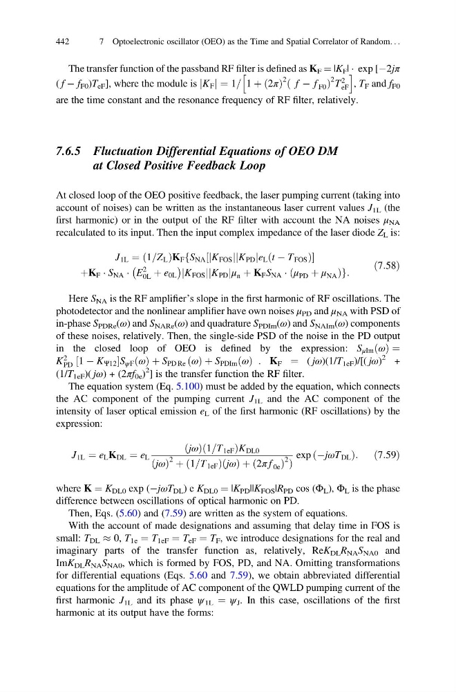
The transfer function of the passband RF filter is defined as K F ¼ |K F | Á exp [À2jπ
( f À f F0 )T eF ], where the module is K F
j j ¼ 1= 1 þ 2π
ð Þ
2 f À f F0
ð
Þ
2 T
2
eF
h
i
, T F and f F0
are the time constant and the resonance frequency of RF filter, relatively.
7.6.5 Fluctuation Differential Equations of OEO DM
at Closed Positive Feedback Loop
At closed loop of the OEO positive feedback, the laser pumping current (taking into
account of noises) can be written as the instantaneous laser current values J 1L (the
first harmonic) or in the output of the RF filter with account the NA noises μ NA
recalculated to its input. Then the input complex impedance of the laser diode Z L is:
J 1L ¼ 1=Z L
ð
ÞK F fS NA K FOS
j
jK PD
j
je L t À T FOS
ð
Þ
½
þK F Á S NA Á E
2
0L þ e 0L
À
Á
K FOS
j
jK PD
j
jμ n þ K F S NA Á μ PD þ μ NA
ð
Þ g :
ð7:58Þ
Here S NA is the RF amplifier’s slope in the first harmonic of RF oscillations. The
photodetector and the nonlinear amplifier have own noises μ PD and μ NA with PSD of
in-phase S PDRe (ω) and S NARe (ω) and quadrature S PDIm (ω) and S NAIm (ω) components
of these noises, relatively. Then, the single-side PSD of the noise in the PD output
in the closed loop of OEO is defined by the expression: S μIm ω
ð Þ ¼
K
2
PD 1 À K Ψ12
½
S ψF ω
ð Þ þ S PD Re ω
ð Þ þ S PDIm ω
ð Þ . K F ¼ ( jω)(1/T 1eF )/[( jω)
2 +
(1/T 1eF )( jω) + (2πf 0e )
2 ] is the transfer function the RF filter.
The equation system (Eq. 5.100) must be added by the equation, which connects
the AC component of the pumping current J 1L and the AC component of the
intensity of laser optical emission e L of the first harmonic (RF oscillations) by the
expression:
J 1L ¼ e L K DL ¼ e L
jω
ð Þ 1=T 1eF
ð
ÞK DL0
jω
ð Þ
2 þ 1=T 1eF
ð
Þ jω
ð Þ þ 2π f 0e
ð
Þ
2 Þ
exp ÀjωT DL
ð
Þ :
ð7:59Þ
where K ¼ K DL0 exp (ÀjωT DL ) e K DL0 ¼ |K PD ||K FOS |R PD cos (Φ L ), Φ L is the phase
difference between oscillations of optical harmonic on PD.
Then, Eqs. (5.60) and (7.59) are written as the system of equations.
With the account of made designations and assuming that delay time in FOS is
small: T DL % 0, T 1e ¼ T 1eF ¼ T eF ¼ T F , we introduce designations for the real and
imaginary parts of the transfer function as, relatively, ReK DL R NA S NA0 and
ImK DL R NA S NA0 , which is formed by FOS, PD, and NA. Omitting transformations
for differential equations (Eqs. 5.60 and 7.59), we obtain abbreviated differential
equations for the amplitude of AC component of the QWLD pumping current of the
first harmonic J 1L and its phase ψ 1L ¼ ψ J . In this case, oscillations of the first
harmonic at its output have the forms:
442
7 Optoelectronic oscillator (OEO) as the Time and Spatial Correlator of Random. . .
( f À f F0 )T eF ], where the module is K F
j j ¼ 1= 1 þ 2π
ð Þ
2 f À f F0
ð
Þ
2 T
2
eF
h
i
, T F and f F0
are the time constant and the resonance frequency of RF filter, relatively.
7.6.5 Fluctuation Differential Equations of OEO DM
at Closed Positive Feedback Loop
At closed loop of the OEO positive feedback, the laser pumping current (taking into
account of noises) can be written as the instantaneous laser current values J 1L (the
first harmonic) or in the output of the RF filter with account the NA noises μ NA
recalculated to its input. Then the input complex impedance of the laser diode Z L is:
J 1L ¼ 1=Z L
ð
ÞK F fS NA K FOS
j
jK PD
j
je L t À T FOS
ð
Þ
½
þK F Á S NA Á E
2
0L þ e 0L
À
Á
K FOS
j
jK PD
j
jμ n þ K F S NA Á μ PD þ μ NA
ð
Þ g :
ð7:58Þ
Here S NA is the RF amplifier’s slope in the first harmonic of RF oscillations. The
photodetector and the nonlinear amplifier have own noises μ PD and μ NA with PSD of
in-phase S PDRe (ω) and S NARe (ω) and quadrature S PDIm (ω) and S NAIm (ω) components
of these noises, relatively. Then, the single-side PSD of the noise in the PD output
in the closed loop of OEO is defined by the expression: S μIm ω
ð Þ ¼
K
2
PD 1 À K Ψ12
½
S ψF ω
ð Þ þ S PD Re ω
ð Þ þ S PDIm ω
ð Þ . K F ¼ ( jω)(1/T 1eF )/[( jω)
2 +
(1/T 1eF )( jω) + (2πf 0e )
2 ] is the transfer function the RF filter.
The equation system (Eq. 5.100) must be added by the equation, which connects
the AC component of the pumping current J 1L and the AC component of the
intensity of laser optical emission e L of the first harmonic (RF oscillations) by the
expression:
J 1L ¼ e L K DL ¼ e L
jω
ð Þ 1=T 1eF
ð
ÞK DL0
jω
ð Þ
2 þ 1=T 1eF
ð
Þ jω
ð Þ þ 2π f 0e
ð
Þ
2 Þ
exp ÀjωT DL
ð
Þ :
ð7:59Þ
where K ¼ K DL0 exp (ÀjωT DL ) e K DL0 ¼ |K PD ||K FOS |R PD cos (Φ L ), Φ L is the phase
difference between oscillations of optical harmonic on PD.
Then, Eqs. (5.60) and (7.59) are written as the system of equations.
With the account of made designations and assuming that delay time in FOS is
small: T DL % 0, T 1e ¼ T 1eF ¼ T eF ¼ T F , we introduce designations for the real and
imaginary parts of the transfer function as, relatively, ReK DL R NA S NA0 and
ImK DL R NA S NA0 , which is formed by FOS, PD, and NA. Omitting transformations
for differential equations (Eqs. 5.60 and 7.59), we obtain abbreviated differential
equations for the amplitude of AC component of the QWLD pumping current of the
first harmonic J 1L and its phase ψ 1L ¼ ψ J . In this case, oscillations of the first
harmonic at its output have the forms:
442
7 Optoelectronic oscillator (OEO) as the Time and Spatial Correlator of Random. . .