

At increase of χ, the accompanied parasite amplitude modulation of the generation signal decreases. When OEO with differential RF FODL is used as the retuning
source of RF oscillations, and also as the functional transducer of physical quantities,
we must take into consideration that the maximal slope of transformation S f gen ¼
Δ f gen =Δα ¼ Δ f gen =Δx, takes place at α closed to 0.5 (Fig. 7.24b), where Δf gen , Δα
are small increments. At that, the transformation characteristic is close to linear.
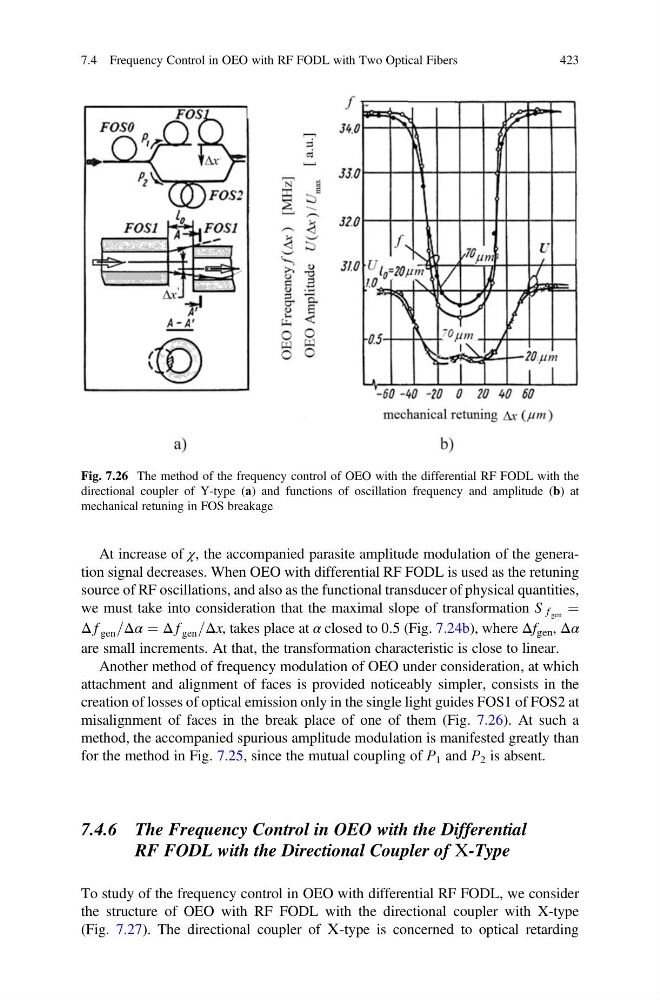
Another method of frequency modulation of OEO under consideration, at which
attachment and alignment of faces is provided noticeably simpler, consists in the
creation of losses of optical emission only in the single light guides FOS1 of FOS2 at
misalignment of faces in the break place of one of them (Fig. 7.26). At such a
method, the accompanied spurious amplitude modulation is manifested greatly than
for the method in Fig. 7.25, since the mutual coupling of Р 1 and Р 2 is absent.
7.4.6 The Frequency Control in OEO with the Differential
RF FODL with the Directional Coupler of Х-Type
To study of the frequency control in OEO with differential RF FODL, we consider
the structure of OEO with RF FODL with the directional coupler with X-type
(Fig. 7.27). The directional coupler of Х-type is concerned to optical retarding
Fig. 7.26 The method of the frequency control of OEO with the differential RF FODL with the
directional coupler of Y-type (а) and functions of oscillation frequency and amplitude (b) at
mechanical retuning in FOS breakage
7.4 Frequency Control in OEO with RF FODL with Two Optical Fibers
423
source of RF oscillations, and also as the functional transducer of physical quantities,
we must take into consideration that the maximal slope of transformation S f gen ¼
Δ f gen =Δα ¼ Δ f gen =Δx, takes place at α closed to 0.5 (Fig. 7.24b), where Δf gen , Δα
are small increments. At that, the transformation characteristic is close to linear.
Another method of frequency modulation of OEO under consideration, at which
attachment and alignment of faces is provided noticeably simpler, consists in the
creation of losses of optical emission only in the single light guides FOS1 of FOS2 at
misalignment of faces in the break place of one of them (Fig. 7.26). At such a
method, the accompanied spurious amplitude modulation is manifested greatly than
for the method in Fig. 7.25, since the mutual coupling of Р 1 and Р 2 is absent.
7.4.6 The Frequency Control in OEO with the Differential
RF FODL with the Directional Coupler of Х-Type
To study of the frequency control in OEO with differential RF FODL, we consider
the structure of OEO with RF FODL with the directional coupler with X-type
(Fig. 7.27). The directional coupler of Х-type is concerned to optical retarding
Fig. 7.26 The method of the frequency control of OEO with the differential RF FODL with the
directional coupler of Y-type (а) and functions of oscillation frequency and amplitude (b) at
mechanical retuning in FOS breakage
7.4 Frequency Control in OEO with RF FODL with Two Optical Fibers
423