

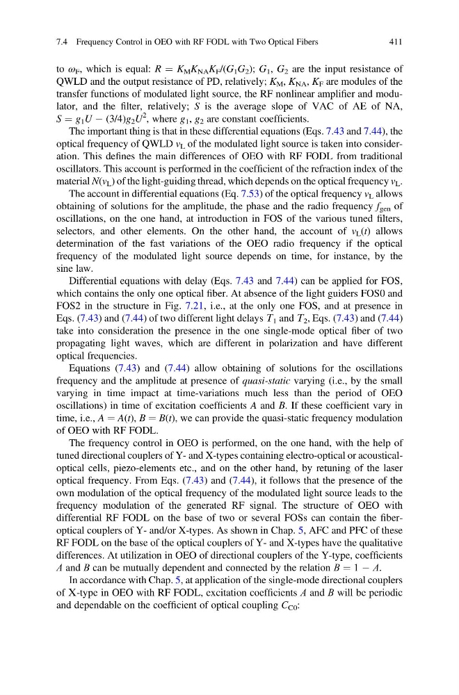
to ω F , which is equal: R ¼ K M K NA K F /(G 1 G 2 ); G 1 , G 2 are the input resistance of
QWLD and the output resistance of PD, relatively; K M , K NA , K F are modules of the
transfer functions of modulated light source, the RF nonlinear amplifier and modulator, and the filter, relatively; S is the average slope of VAC of AE of NA,
S ¼ g 1 U À (3/4)g 2 U
2 , where g 1 , g 2 are constant coefficients.
The important thing is that in these differential equations (Eqs. 7.43 and 7.44), the
optical frequency of QWLD v L of the modulated light source is taken into consideration. This defines the main differences of OEO with RF FODL from traditional
oscillators. This account is performed in the coefficient of the refraction index of the
material N(v L ) of the light-guiding thread, which depends on the optical frequency v L .
The account in differential equations (Eq. 7.53) of the optical frequency v L allows
obtaining of solutions for the amplitude, the phase and the radio frequency f gen of
oscillations, on the one hand, at introduction in FOS of the various tuned filters,
selectors, and other elements. On the other hand, the account of v L (t) allows
determination of the fast variations of the OEO radio frequency if the optical
frequency of the modulated light source depends on time, for instance, by the
sine law.
Differential equations with delay (Eqs. 7.43 and 7.44) can be applied for FOS,
which contains the only one optical fiber. At absence of the light guiders FOS0 and
FOS2 in the structure in Fig. 7.21, i.e., at the only one FOS, and at presence in
Eqs. (7.43) and (7.44) of two different light delays Т 1 and Т 2 , Eqs. (7.43) and (7.44)
take into consideration the presence in the one single-mode optical fiber of two
propagating light waves, which are different in polarization and have different
optical frequencies.
Equations (7.43) and (7.44) allow obtaining of solutions for the oscillations
frequency and the amplitude at presence of quasi-static varying (i.e., by the small
varying in time impact at time-variations much less than the period of OEO
oscillations) in time of excitation coefficients A and B. If these coefficient vary in
time, i.e., A ¼ A(t), B ¼ B(t), we can provide the quasi-static frequency modulation
of OEO with RF FODL.
The frequency control in OEO is performed, on the one hand, with the help of
tuned directional couplers of Y- and X-types containing electro-optical or acousticaloptical cells, piezo-elements etc., and on the other hand, by retuning of the laser
optical frequency. From Eqs. (7.43) and (7.44), it follows that the presence of the
own modulation of the optical frequency of the modulated light source leads to the
frequency modulation of the generated RF signal. The structure of OEO with
differential RF FODL on the base of two or several FOSs can contain the fiberoptical couplers of Y- and/or X-types. As shown in Chap. 5, AFC and PFC of these
RF FODL on the base of the optical couplers of Y- and X-types have the qualitative
differences. At utilization in OEO of directional couplers of the Y-type, coefficients
А and В can be mutually dependent and connected by the relation В ¼ 1 À А.
In accordance with Chap. 5, at application of the single-mode directional couplers
of Х-type in OEO with RF FODL, excitation coefficients А and В will be periodic
and dependable on the coefficient of optical coupling C C0 :
7.4 Frequency Control in OEO with RF FODL with Two Optical Fibers
411
QWLD and the output resistance of PD, relatively; K M , K NA , K F are modules of the
transfer functions of modulated light source, the RF nonlinear amplifier and modulator, and the filter, relatively; S is the average slope of VAC of AE of NA,
S ¼ g 1 U À (3/4)g 2 U
2 , where g 1 , g 2 are constant coefficients.
The important thing is that in these differential equations (Eqs. 7.43 and 7.44), the
optical frequency of QWLD v L of the modulated light source is taken into consideration. This defines the main differences of OEO with RF FODL from traditional
oscillators. This account is performed in the coefficient of the refraction index of the
material N(v L ) of the light-guiding thread, which depends on the optical frequency v L .
The account in differential equations (Eq. 7.53) of the optical frequency v L allows
obtaining of solutions for the amplitude, the phase and the radio frequency f gen of
oscillations, on the one hand, at introduction in FOS of the various tuned filters,
selectors, and other elements. On the other hand, the account of v L (t) allows
determination of the fast variations of the OEO radio frequency if the optical
frequency of the modulated light source depends on time, for instance, by the
sine law.
Differential equations with delay (Eqs. 7.43 and 7.44) can be applied for FOS,
which contains the only one optical fiber. At absence of the light guiders FOS0 and
FOS2 in the structure in Fig. 7.21, i.e., at the only one FOS, and at presence in
Eqs. (7.43) and (7.44) of two different light delays Т 1 and Т 2 , Eqs. (7.43) and (7.44)
take into consideration the presence in the one single-mode optical fiber of two
propagating light waves, which are different in polarization and have different
optical frequencies.
Equations (7.43) and (7.44) allow obtaining of solutions for the oscillations
frequency and the amplitude at presence of quasi-static varying (i.e., by the small
varying in time impact at time-variations much less than the period of OEO
oscillations) in time of excitation coefficients A and B. If these coefficient vary in
time, i.e., A ¼ A(t), B ¼ B(t), we can provide the quasi-static frequency modulation
of OEO with RF FODL.
The frequency control in OEO is performed, on the one hand, with the help of
tuned directional couplers of Y- and X-types containing electro-optical or acousticaloptical cells, piezo-elements etc., and on the other hand, by retuning of the laser
optical frequency. From Eqs. (7.43) and (7.44), it follows that the presence of the
own modulation of the optical frequency of the modulated light source leads to the
frequency modulation of the generated RF signal. The structure of OEO with
differential RF FODL on the base of two or several FOSs can contain the fiberoptical couplers of Y- and/or X-types. As shown in Chap. 5, AFC and PFC of these
RF FODL on the base of the optical couplers of Y- and X-types have the qualitative
differences. At utilization in OEO of directional couplers of the Y-type, coefficients
А and В can be mutually dependent and connected by the relation В ¼ 1 À А.
In accordance with Chap. 5, at application of the single-mode directional couplers
of Х-type in OEO with RF FODL, excitation coefficients А and В will be periodic
and dependable on the coefficient of optical coupling C C0 :
7.4 Frequency Control in OEO with RF FODL with Two Optical Fibers
411