

S 0 ¼ S 01 þ jS 02
ð7:20Þ
and is determined from the relation:
S 0 ¼ 0:5 À1 Æ
ffiffiffiffiffiffiffiffiffiffiffiffiffiffiffiffiffiffiffiffiffiffiffiffiffiffiffiffiffiffiffiffiffiffiffiffiffiffiffiffiffiffiffiffiffiffiffiffiffiffiffiffiffiffiffiffiffiffiffiffiffiffiffiffi
1 þ 8 2πν
ð
Þ
2 l
2
c 2 Γ 0 2ε 2 À ε 1 À ε 3
ð
Þ
r
"
#
:
ð7:21Þ
In this formula, the sign “+” corresponds to the case ε 2 ! Re ε 1 , ε 2 ! Re ε 3 ,
when the waveguide properties are caused by the real part of the permittivity, the
sign “À” corresponds to the case, when the real part corresponds to the antiwaveguide effect and the waveguide properties of the structure are supported
owing to the amplification, i.e., due to the contribution of the imaginary part of ε 2
(Imε 2 < 0).
7.2.2 The Field in the Near Zone for the Main Mode
The field in the near zone for the fundamental zone is given by the expression:
E Y0 y
ð Þ ¼ E 0 y
ð Þ exp jΦ y
ð Þ
½
,
ð7:22Þ
where E 0 ( y) is the amplitude, Φ( y) is the phase of the EMF strength. At that, for the
main mode in the symmetric case (ε 3 ¼ ε 1 and therefore a 0 ¼ 0), we obtain formulas
as:
E 0 y
ð Þ ¼
E 00
ch y=l
ð Þ
½
S 01
¼
E 00
0:5 exp y=l
ð Þþ 0:5 exp Ày=l
ð
Þ
½
S 01
,
ð7:23Þ
Φ y
ð Þ ¼ S 02 ln ch y=l
ð Þ
½
¼S 02 ln 0:5 exp y=l
ð Þ þ 0:5 exp Ày=l
ð
Þ
½
f
g ,
ð7:24Þ
where E 00 ¼ E 0 (y ¼ 0), the function of the hyperbolic cosine is equal to:
ch y=2l
ð
Þ ¼ 0:5 Á exp y=2l
ð
Þþ exp Ày=2l
ð
Þ
½
:
ð7:25Þ
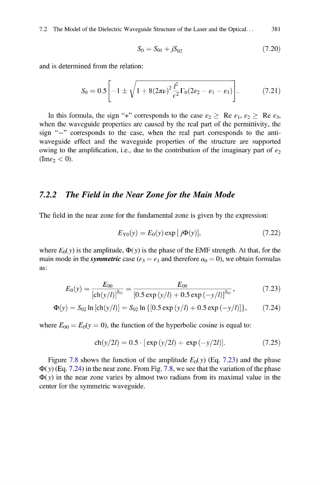
Figure 7.8 shows the function of the amplitude E 0 ( y) (Eq. 7.23) and the phase
Φ( y) (Eq. 7.24) in the near zone. From Fig. 7.8, we see that the variation of the phase
Φ( y) in the near zone varies by almost two radians from its maximal value in the
center for the symmetric waveguide.
7.2 The Model of the Dielectric Waveguide Structure of the Laser and the Optical. . .
381
ð7:20Þ
and is determined from the relation:
S 0 ¼ 0:5 À1 Æ
ffiffiffiffiffiffiffiffiffiffiffiffiffiffiffiffiffiffiffiffiffiffiffiffiffiffiffiffiffiffiffiffiffiffiffiffiffiffiffiffiffiffiffiffiffiffiffiffiffiffiffiffiffiffiffiffiffiffiffiffiffiffiffiffi
1 þ 8 2πν
ð
Þ
2 l
2
c 2 Γ 0 2ε 2 À ε 1 À ε 3
ð
Þ
r
"
#
:
ð7:21Þ
In this formula, the sign “+” corresponds to the case ε 2 ! Re ε 1 , ε 2 ! Re ε 3 ,
when the waveguide properties are caused by the real part of the permittivity, the
sign “À” corresponds to the case, when the real part corresponds to the antiwaveguide effect and the waveguide properties of the structure are supported
owing to the amplification, i.e., due to the contribution of the imaginary part of ε 2
(Imε 2 < 0).
7.2.2 The Field in the Near Zone for the Main Mode
The field in the near zone for the fundamental zone is given by the expression:
E Y0 y
ð Þ ¼ E 0 y
ð Þ exp jΦ y
ð Þ
½
,
ð7:22Þ
where E 0 ( y) is the amplitude, Φ( y) is the phase of the EMF strength. At that, for the
main mode in the symmetric case (ε 3 ¼ ε 1 and therefore a 0 ¼ 0), we obtain formulas
as:
E 0 y
ð Þ ¼
E 00
ch y=l
ð Þ
½
S 01
¼
E 00
0:5 exp y=l
ð Þþ 0:5 exp Ày=l
ð
Þ
½
S 01
,
ð7:23Þ
Φ y
ð Þ ¼ S 02 ln ch y=l
ð Þ
½
¼S 02 ln 0:5 exp y=l
ð Þ þ 0:5 exp Ày=l
ð
Þ
½
f
g ,
ð7:24Þ
where E 00 ¼ E 0 (y ¼ 0), the function of the hyperbolic cosine is equal to:
ch y=2l
ð
Þ ¼ 0:5 Á exp y=2l
ð
Þþ exp Ày=2l
ð
Þ
½
:
ð7:25Þ
Figure 7.8 shows the function of the amplitude E 0 ( y) (Eq. 7.23) and the phase
Φ( y) (Eq. 7.24) in the near zone. From Fig. 7.8, we see that the variation of the phase
Φ( y) in the near zone varies by almost two radians from its maximal value in the
center for the symmetric waveguide.
7.2 The Model of the Dielectric Waveguide Structure of the Laser and the Optical. . .
381