

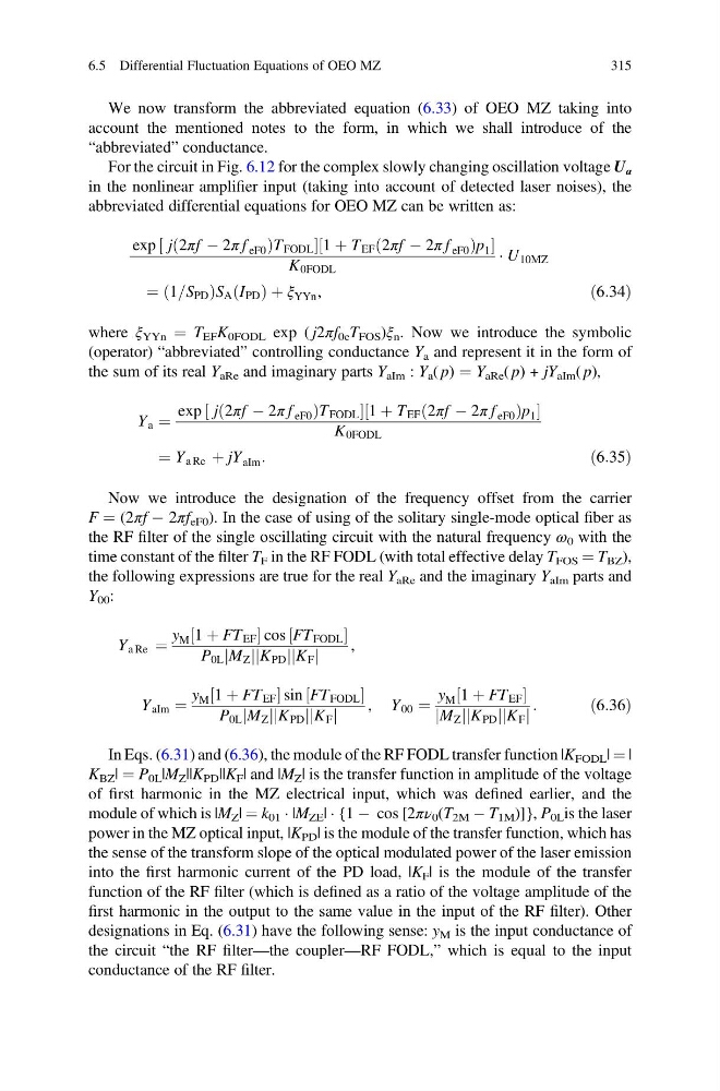
We now transform the abbreviated equation (6.33) of OEO MZ taking into
account the mentioned notes to the form, in which we shall introduce of the
“abbreviated” conductance.
For the circuit in Fig. 6.12 for the complex slowly changing oscillation voltage U а
in the nonlinear amplifier input (taking into account of detected laser noises), the
abbreviated differential equations for OEO MZ can be written as:
exp j 2πf À 2π f eF0
ð
Þ T FODL
½
1 þ T EF 2πf À 2π f eF0
ð
Þ p 1
½
K 0FODL
Á U 10MZ
¼ 1=S PD
ð
ÞS A I PD
ð Þþξ YYn ,
ð6:34Þ
where ξ YYn ¼ T EF K 0FODL exp ( j2πf 0e T FOS )ξ n . Now we introduce the symbolic
(operator) “abbreviated” controlling conductance Y a and represent it in the form of
the sum of its real Y aRe and imaginary parts Y aIm : Y a ( p) ¼ Y aRe ( p) + jY aIm ( p),
Y a ¼
exp j 2πf À 2π f eF0
ð
Þ T FODL
½
1 þ T EF 2πf À 2π f eF0
ð
Þ p 1
½
K 0FODL
¼ Y a Re þ jY aIm :
ð6:35Þ
Now we introduce the designation of the frequency offset from the carrier
F ¼ (2πf À 2πf eF0 ). In the case of using of the solitary single-mode optical fiber as
the RF filter of the single oscillating circuit with the natural frequency ω 0 with the
time constant of the filter T F in the RF FODL (with total effective delay T FOS ¼ T BZ ),
the following expressions are true for the real Y aRe and the imaginary Y aIm parts and
Y 00 :
Y a Re ¼
y M 1 þ FT EF
½
cos FT FODL
½
P 0L M Z
j j K PD
j
j K F
j j
,
Y aIm ¼
y M 1 þ FT EF
½
sin FT FODL
½
P 0L M Z
j j K PD
j
j K F
j j
, Y 00 ¼
y M 1 þ FT EF
½
M Z
j j K PD
j
j K F
j j
:
ð6:36Þ
In Eqs. (6.31) and (6.36), the module of the RF FODL transfer function |K FODL | ¼ |
K BZ | ¼ P 0L |M Z ||K PD ||K F | and |M Z | is the transfer function in amplitude of the voltage
of first harmonic in the MZ electrical input, which was defined earlier, and the
module of which is |M Z | ¼ k 01 Á |M ZE | Á {1 À cos [2πν 0 (T 2M À T 1M )]}, P 0L is the laser
power in the MZ optical input, |K PD | is the module of the transfer function, which has
the sense of the transform slope of the optical modulated power of the laser emission
into the first harmonic current of the PD load, |K F | is the module of the transfer
function of the RF filter (which is defined as a ratio of the voltage amplitude of the
first harmonic in the output to the same value in the input of the RF filter). Other
designations in Eq. (6.31) have the following sense: y M is the input conductance of
the circuit “the RF filter—the coupler—RF FODL,” which is equal to the input
conductance of the RF filter.
6.5 Differential Fluctuation Equations of OEO MZ
315
account the mentioned notes to the form, in which we shall introduce of the
“abbreviated” conductance.
For the circuit in Fig. 6.12 for the complex slowly changing oscillation voltage U а
in the nonlinear amplifier input (taking into account of detected laser noises), the
abbreviated differential equations for OEO MZ can be written as:
exp j 2πf À 2π f eF0
ð
Þ T FODL
½
1 þ T EF 2πf À 2π f eF0
ð
Þ p 1
½
K 0FODL
Á U 10MZ
¼ 1=S PD
ð
ÞS A I PD
ð Þþξ YYn ,
ð6:34Þ
where ξ YYn ¼ T EF K 0FODL exp ( j2πf 0e T FOS )ξ n . Now we introduce the symbolic
(operator) “abbreviated” controlling conductance Y a and represent it in the form of
the sum of its real Y aRe and imaginary parts Y aIm : Y a ( p) ¼ Y aRe ( p) + jY aIm ( p),
Y a ¼
exp j 2πf À 2π f eF0
ð
Þ T FODL
½
1 þ T EF 2πf À 2π f eF0
ð
Þ p 1
½
K 0FODL
¼ Y a Re þ jY aIm :
ð6:35Þ
Now we introduce the designation of the frequency offset from the carrier
F ¼ (2πf À 2πf eF0 ). In the case of using of the solitary single-mode optical fiber as
the RF filter of the single oscillating circuit with the natural frequency ω 0 with the
time constant of the filter T F in the RF FODL (with total effective delay T FOS ¼ T BZ ),
the following expressions are true for the real Y aRe and the imaginary Y aIm parts and
Y 00 :
Y a Re ¼
y M 1 þ FT EF
½
cos FT FODL
½
P 0L M Z
j j K PD
j
j K F
j j
,
Y aIm ¼
y M 1 þ FT EF
½
sin FT FODL
½
P 0L M Z
j j K PD
j
j K F
j j
, Y 00 ¼
y M 1 þ FT EF
½
M Z
j j K PD
j
j K F
j j
:
ð6:36Þ
In Eqs. (6.31) and (6.36), the module of the RF FODL transfer function |K FODL | ¼ |
K BZ | ¼ P 0L |M Z ||K PD ||K F | and |M Z | is the transfer function in amplitude of the voltage
of first harmonic in the MZ electrical input, which was defined earlier, and the
module of which is |M Z | ¼ k 01 Á |M ZE | Á {1 À cos [2πν 0 (T 2M À T 1M )]}, P 0L is the laser
power in the MZ optical input, |K PD | is the module of the transfer function, which has
the sense of the transform slope of the optical modulated power of the laser emission
into the first harmonic current of the PD load, |K F | is the module of the transfer
function of the RF filter (which is defined as a ratio of the voltage amplitude of the
first harmonic in the output to the same value in the input of the RF filter). Other
designations in Eq. (6.31) have the following sense: y M is the input conductance of
the circuit “the RF filter—the coupler—RF FODL,” which is equal to the input
conductance of the RF filter.
6.5 Differential Fluctuation Equations of OEO MZ
315