

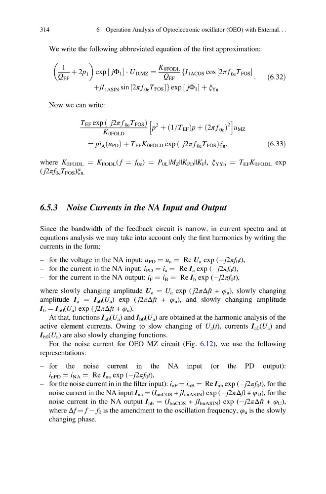
We write the following abbreviated equation of the first approximation:
1
Q EF
þ 2p 1
exp jΦ 1
½
ÁU 10MZ ¼
K 0FODL
Q EF
fI 1ACOS cos 2π f 0e T FOS
½
þjI 1ASIN sin 2π f 0e T FOS
½
gexp jΦ 1
½
þξ Yn
:
ð6:32Þ
Now we can write:
T EF exp j2π f 0e T FOS
ð
Þ
K 0FOLD
p
2
þ 1=T EF
ð
Þp þ 2π f 0e
ð
Þ
2
h
i
u MZ
¼ pi A u PD
ð ÞþT EF K 0FOLD exp j2π f 0e T FOS
ð
Þ ξ n ,
ð6:33Þ
where K 0FODL ¼ K FODL ( f ¼ f 0e ) ¼ P 0L |M Z ||K PD ||K F |, ξ YYn ¼ T EF K 0FODL exp
( j2πf 0e T FOS )ξ n.
6.5.3 Noise Currents in the NA Input and Output
Since the bandwidth of the feedback circuit is narrow, in current spectra and at
equations analysis we may take into account only the first harmonics by writing the
currents in the form:
– for the voltage in the NA input: u PD ¼ u a ¼ Re U a exp (Àj2πf 0 t),
– for the current in the NA input: i PD ¼ i a ¼ Re I a exp (Àj2πf 0 t),
– for the current in the NA output: i F ¼ i B ¼ Re I b exp (Àj2πf 0 t),
where slowly changing amplitude U a ¼ U a exp ( j2πΔft + φ u ), slowly changing
amplitude I a ¼ I a0 (U a ) exp ( j2πΔft + φ u ), and slowly changing amplitude
I b ¼ I b0 (U a ) exp ( j2πΔft + φ u ).
At that, functions I a0 (U a ) and I b0 (U a ) are obtained at the harmonic analysis of the
active element currents. Owing to slow changing of U a (t), currents I a0 (U a ) and
I b0 (U a ) are also slowly changing functions.
For the noise current for OEO MZ circuit (Fig. 6.12), we use the following
representations:
– for the noise current in the NA input (or the PD output):
i nPD ¼ i NA ¼ Re I na exp (Àj2πf 0 t),
– for the noise current in in the filter input): i nF ¼ i nB ¼ Re I nb exp (Àj2πf 0 t), for the
noise current in the NA input I na ¼ (I anCOS + jI anASIN ) exp (Àj2πΔft + φ U ), for the
noise current in the NA output I nb ¼ (I bnCOS + jI bnASIN ) exp (Àj2πΔft + φ U ),
where Δf ¼ f À f 0 is the amendment to the oscillation frequency, φ u is the slowly
changing phase.
314
6 Operation Analysis of Optoelectronic oscillator (OEO) with External. . .
1
Q EF
þ 2p 1
exp jΦ 1
½
ÁU 10MZ ¼
K 0FODL
Q EF
fI 1ACOS cos 2π f 0e T FOS
½
þjI 1ASIN sin 2π f 0e T FOS
½
gexp jΦ 1
½
þξ Yn
:
ð6:32Þ
Now we can write:
T EF exp j2π f 0e T FOS
ð
Þ
K 0FOLD
p
2
þ 1=T EF
ð
Þp þ 2π f 0e
ð
Þ
2
h
i
u MZ
¼ pi A u PD
ð ÞþT EF K 0FOLD exp j2π f 0e T FOS
ð
Þ ξ n ,
ð6:33Þ
where K 0FODL ¼ K FODL ( f ¼ f 0e ) ¼ P 0L |M Z ||K PD ||K F |, ξ YYn ¼ T EF K 0FODL exp
( j2πf 0e T FOS )ξ n.
6.5.3 Noise Currents in the NA Input and Output
Since the bandwidth of the feedback circuit is narrow, in current spectra and at
equations analysis we may take into account only the first harmonics by writing the
currents in the form:
– for the voltage in the NA input: u PD ¼ u a ¼ Re U a exp (Àj2πf 0 t),
– for the current in the NA input: i PD ¼ i a ¼ Re I a exp (Àj2πf 0 t),
– for the current in the NA output: i F ¼ i B ¼ Re I b exp (Àj2πf 0 t),
where slowly changing amplitude U a ¼ U a exp ( j2πΔft + φ u ), slowly changing
amplitude I a ¼ I a0 (U a ) exp ( j2πΔft + φ u ), and slowly changing amplitude
I b ¼ I b0 (U a ) exp ( j2πΔft + φ u ).
At that, functions I a0 (U a ) and I b0 (U a ) are obtained at the harmonic analysis of the
active element currents. Owing to slow changing of U a (t), currents I a0 (U a ) and
I b0 (U a ) are also slowly changing functions.
For the noise current for OEO MZ circuit (Fig. 6.12), we use the following
representations:
– for the noise current in the NA input (or the PD output):
i nPD ¼ i NA ¼ Re I na exp (Àj2πf 0 t),
– for the noise current in in the filter input): i nF ¼ i nB ¼ Re I nb exp (Àj2πf 0 t), for the
noise current in the NA input I na ¼ (I anCOS + jI anASIN ) exp (Àj2πΔft + φ U ), for the
noise current in the NA output I nb ¼ (I bnCOS + jI bnASIN ) exp (Àj2πΔft + φ U ),
where Δf ¼ f À f 0 is the amendment to the oscillation frequency, φ u is the slowly
changing phase.
314
6 Operation Analysis of Optoelectronic oscillator (OEO) with External. . .