

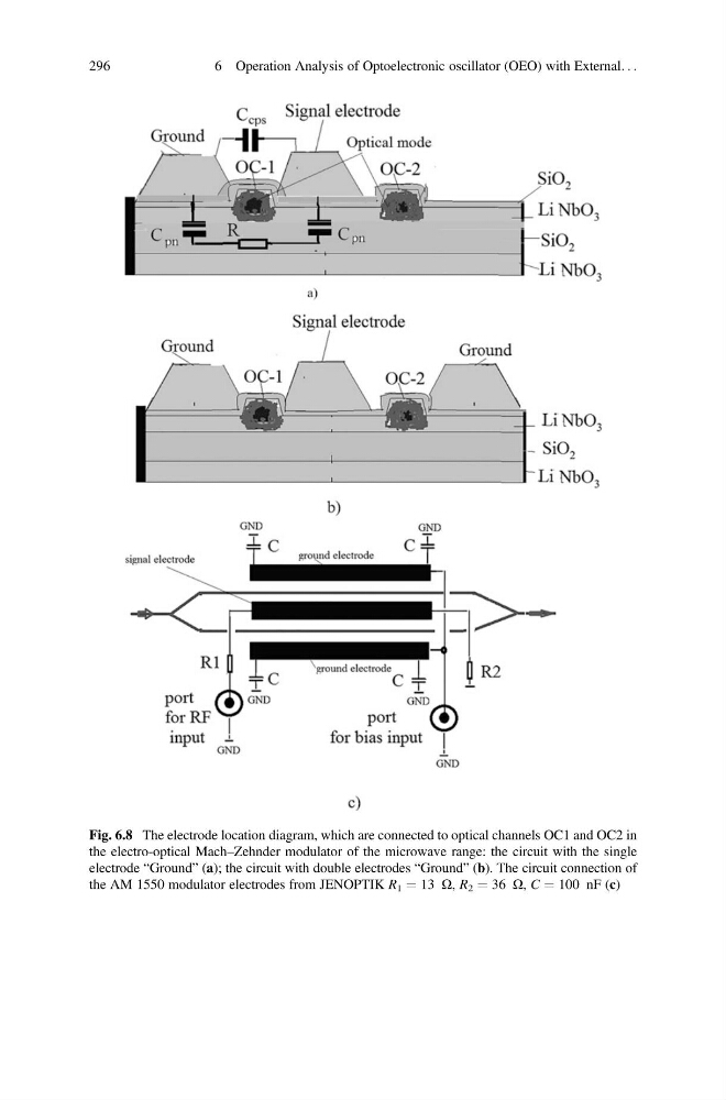
Fig. 6.8 The electrode location diagram, which are connected to optical channels OC1 and OC2 in
the electro-optical Mach–Zehnder modulator of the microwave range: the circuit with the single
electrode “Ground” (a); the circuit with double electrodes “Ground” (b). The circuit connection of
the AM 1550 modulator electrodes from JENOPTIK R 1 ¼ 13 Ω, R 2 ¼ 36 Ω, C ¼ 100 nF (c)
296
6 Operation Analysis of Optoelectronic oscillator (OEO) with External. . .
the electro-optical Mach–Zehnder modulator of the microwave range: the circuit with the single
electrode “Ground” (a); the circuit with double electrodes “Ground” (b). The circuit connection of
the AM 1550 modulator electrodes from JENOPTIK R 1 ¼ 13 Ω, R 2 ¼ 36 Ω, C ¼ 100 nF (c)
296
6 Operation Analysis of Optoelectronic oscillator (OEO) with External. . .