

steady-state frequency can be found at the solution of the phase and amplitude
balance equations (Eq. 3.44). At that, the laser generation frequency (the intercept
point of plots φ OA and φ OF is shown by the point in Fig. 3.17c) slightly exceeds the
value of the own natural resonance frequency.
Let us represent the instantaneous values of voltages (Fig. 3.2c) u PD (t), u F (t),
u A (t), u C (t) in the time form: for MZ input u MZ ¼ U 10MZ Re[exp( j2πft À Φ MZ )]; for
PD output u PD ¼ U 10PD Re[exp( j2πft À Φ PD )]; for RF filter output u F ¼ U 10F Re
[exp( j2πft À Φ F )]; for amplifier output u A ¼ U 10A Re[exp( j2πft À Φ A )]; for coupler
output u C ¼ U 10C Re[exp( j2πft À Φ C )]; where U 10MZ ; U 10PD ; U 10F ; U 10A ; U 10C are
amplitudes of the first harmonics, Φ MZ ; Φ PD ; Φ F ; Φ A ; Φ C are the appropriate phase
incursions.
We designate
5 as U MZ , U PD , U F , U A , U C the complex quantities of the appropriate
variables of u PD (t), u F (t), u A (t), u C (t). We introduce the complex transfer function of
RF FODL K FODL : K FODL ¼ U PD /U MZ ¼ |K FODL |exp(Àj2πfT FOS À jΦ FOS ), where
T FOS is the delay time in the optical fiber system, Φ FOS is the PFC of FODL without
account of the phase incursion in FOS, |K FODL | is the module of RF FODL transfer
function. Let us introduce the complex transfer functions for blocks F, A, C,
relatively, K F , K A , K C : K F ¼ U F /U PD ; K A ¼ U A /U F ; K C ¼ U MZ /U A .
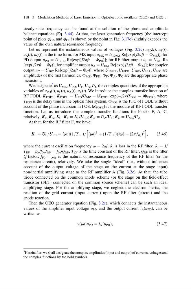
At that, for the RF filter F, we have:
K F ¼ U F =U PD ¼ jω
ð Þ 1=T EF
ð
Þ= jω
ð Þ
2 þ 1=T EF
ð
Þ jω
ð Þ þ 2π f 0e
ð
Þ
2
h
i
,
ð3:46Þ
where the current oscillation frequency ω ¼ 2πf, δ e is loss in the RF filter, δ e ¼ 1/
T EF ¼ f 0e /f 0e T EF ¼ f 0e /Q EF , T EF is the time constant of the RF filter, Q EF is the filter
Q-factor, f F0 ¼ f 0e is the natural or resonance frequency of the RF filter (or the
resonance circuit), relatively. We take the single “ideal” (i.e., without influence
account of the output voltage of the stage on the current at the stage input)
non-inertial amplifying stage as the RF amplifier A (Fig. 3.2c). At that, the tube
triode connected on the common anode scheme (or the stage on the field-effect
transistor (FET) connected on the common source scheme) can be such an ideal
amplifying stage. For the amplifying stage, we neglect the electron inertia, the
reaction of the grid current (input current) upon the RF filter (circuit) and the
anode reaction.
Then the OEO generator equation (Fig. 3.2c), which connects the instantaneous
values of the amplifier input voltage u PD and the output current i A (u PD ), can be
written as
y jω
ð Þu PD ¼ i A u PD
ð Þ,
ð3:47Þ
5 Hereinafter, we shall designate the complex amplitudes (input and output) of currents, voltages and
the complex functions by the bold symbols.
118 3 Modulation Methods of Laser Emission in Optoelectronic oscillator (OEO) and OEO. . .
balance equations (Eq. 3.44). At that, the laser generation frequency (the intercept
point of plots φ OA and φ OF is shown by the point in Fig. 3.17c) slightly exceeds the
value of the own natural resonance frequency.
Let us represent the instantaneous values of voltages (Fig. 3.2c) u PD (t), u F (t),
u A (t), u C (t) in the time form: for MZ input u MZ ¼ U 10MZ Re[exp( j2πft À Φ MZ )]; for
PD output u PD ¼ U 10PD Re[exp( j2πft À Φ PD )]; for RF filter output u F ¼ U 10F Re
[exp( j2πft À Φ F )]; for amplifier output u A ¼ U 10A Re[exp( j2πft À Φ A )]; for coupler
output u C ¼ U 10C Re[exp( j2πft À Φ C )]; where U 10MZ ; U 10PD ; U 10F ; U 10A ; U 10C are
amplitudes of the first harmonics, Φ MZ ; Φ PD ; Φ F ; Φ A ; Φ C are the appropriate phase
incursions.
We designate
5 as U MZ , U PD , U F , U A , U C the complex quantities of the appropriate
variables of u PD (t), u F (t), u A (t), u C (t). We introduce the complex transfer function of
RF FODL K FODL : K FODL ¼ U PD /U MZ ¼ |K FODL |exp(Àj2πfT FOS À jΦ FOS ), where
T FOS is the delay time in the optical fiber system, Φ FOS is the PFC of FODL without
account of the phase incursion in FOS, |K FODL | is the module of RF FODL transfer
function. Let us introduce the complex transfer functions for blocks F, A, C,
relatively, K F , K A , K C : K F ¼ U F /U PD ; K A ¼ U A /U F ; K C ¼ U MZ /U A .
At that, for the RF filter F, we have:
K F ¼ U F =U PD ¼ jω
ð Þ 1=T EF
ð
Þ= jω
ð Þ
2 þ 1=T EF
ð
Þ jω
ð Þ þ 2π f 0e
ð
Þ
2
h
i
,
ð3:46Þ
where the current oscillation frequency ω ¼ 2πf, δ e is loss in the RF filter, δ e ¼ 1/
T EF ¼ f 0e /f 0e T EF ¼ f 0e /Q EF , T EF is the time constant of the RF filter, Q EF is the filter
Q-factor, f F0 ¼ f 0e is the natural or resonance frequency of the RF filter (or the
resonance circuit), relatively. We take the single “ideal” (i.e., without influence
account of the output voltage of the stage on the current at the stage input)
non-inertial amplifying stage as the RF amplifier A (Fig. 3.2c). At that, the tube
triode connected on the common anode scheme (or the stage on the field-effect
transistor (FET) connected on the common source scheme) can be such an ideal
amplifying stage. For the amplifying stage, we neglect the electron inertia, the
reaction of the grid current (input current) upon the RF filter (circuit) and the
anode reaction.
Then the OEO generator equation (Fig. 3.2c), which connects the instantaneous
values of the amplifier input voltage u PD and the output current i A (u PD ), can be
written as
y jω
ð Þu PD ¼ i A u PD
ð Þ,
ð3:47Þ
5 Hereinafter, we shall designate the complex amplitudes (input and output) of currents, voltages and
the complex functions by the bold symbols.
118 3 Modulation Methods of Laser Emission in Optoelectronic oscillator (OEO) and OEO. . .