

the input oscillation E Lin to the output oscillation E Lout of the emission field strength,
is
K OF ¼
E Lout
E Lin
¼
K 1OF Á K 2OF exp α OF L OF þ j2πνL OF n OF =c
ð
Þ
1 À R 1OF Á R 2OF exp α OF L OF þ j2πνL OF n OF =c
ð
Þ
ð3:37Þ
where c is the light speed in vacuum.
The Bragg resonator is formed by the optical structure, in which the refraction
index periodically varies or by the multilayer structures with different refraction
indices (Fig. 2.7). The extreme Q-factors are restricted by the length and losses of the
periodic structure and achieve a million at geometrical length about 3 cm. The high
power density of emission at high Q-factors (10
6 ) [4–8] does not permit to use them
as the linear devices for input powers more than 20–100 μW. Evolution of nonlinear
optical effects and the temperature instability prohibits from qualitative oscillation
selection. Nevertheless, they are acceptable as frequency discriminators (with the
conversion slope 1/Hz) in devices for frequency and phase automatic control of
semiconductor lasers, if the small optical power of 20–100 μW is applied to the
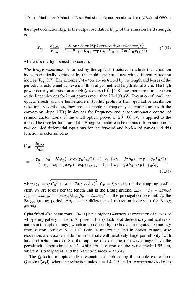
input. The transfer function of the Bragg resonator can be obtained from solution of
two coupled differential equations for the forward and backward waves and this
function is determined as
K OF ¼
E Lout
E Lin
¼
À γ B þ α B À jΔβ B
ð
Þ Áexp γ B L B =2
ð
Þþ À γ B þ α B À jΔβ B
ð
Þ Á exp Àγ B L B =2
ð
Þ
Àγ B þ α B À jΔβ B
ð
Þ Á exp γ B L B
ð
ÞÀ γ B þ α B À jΔβ B
ð
Þ exp Àγ B L B
ð
Þ
,
ð3:38Þ
where γ B ¼
ffiffiffiffiffiffiffiffiffiffiffiffiffiffiffiffiffiffiffiffiffiffiffiffiffiffiffiffiffiffiffiffiffiffiffiffiffiffiffiffiffiffiffiffiffiffiffiffiffiffi ffi
C B
2
þ β B À 2πn 0B =λ 0B
ð
Þ
2
q
, C B ¼ j(Δn 0F /λ B ) is the coupling coefficient, α B are losses per the length unit in the Bragg grating, Δβ B ¼ β B À 2πn 0B /
λ 0B ¼ 2πνn 0B /c À 2πn 0B /λ 0B , β B ¼ 2πνn 0B /c is the propagation constant, λ B the
Bragg grating period, Δn 0F is the difference of refraction indices in the Bragg
grating.
Cylindrical disc resonators [9–11] have higher Q-factors at excitation of waves of
whispering gallery in them. At present, the Q-factors of dielectric cylindrical resonators in the optical range, which are produced by methods of integrated technology
from silicon, achieve 5 Â 10
6 . Both in microwave and in optical ranges, disc
resonators are usually made from materials with relatively large permittivity (with
large refraction index). So, the sapphire discs in the mm-wave range have the
permittivity approximately 12, while for a silicon on the wavelength 1.55 μm,
where it is transparent, and the refraction index n % 3.48.
The Q-factor of optical disc resonators is defined by the simple expression:
Q ¼ 2πn/(α 1 λ), where the refraction index n ¼ 1.4–1.5, and α 1 corresponds to losses
110 3 Modulation Methods of Laser Emission in Optoelectronic oscillator (OEO) and OEO. . .
is
K OF ¼
E Lout
E Lin
¼
K 1OF Á K 2OF exp α OF L OF þ j2πνL OF n OF =c
ð
Þ
1 À R 1OF Á R 2OF exp α OF L OF þ j2πνL OF n OF =c
ð
Þ
ð3:37Þ
where c is the light speed in vacuum.
The Bragg resonator is formed by the optical structure, in which the refraction
index periodically varies or by the multilayer structures with different refraction
indices (Fig. 2.7). The extreme Q-factors are restricted by the length and losses of the
periodic structure and achieve a million at geometrical length about 3 cm. The high
power density of emission at high Q-factors (10
6 ) [4–8] does not permit to use them
as the linear devices for input powers more than 20–100 μW. Evolution of nonlinear
optical effects and the temperature instability prohibits from qualitative oscillation
selection. Nevertheless, they are acceptable as frequency discriminators (with the
conversion slope 1/Hz) in devices for frequency and phase automatic control of
semiconductor lasers, if the small optical power of 20–100 μW is applied to the
input. The transfer function of the Bragg resonator can be obtained from solution of
two coupled differential equations for the forward and backward waves and this
function is determined as
K OF ¼
E Lout
E Lin
¼
À γ B þ α B À jΔβ B
ð
Þ Áexp γ B L B =2
ð
Þþ À γ B þ α B À jΔβ B
ð
Þ Á exp Àγ B L B =2
ð
Þ
Àγ B þ α B À jΔβ B
ð
Þ Á exp γ B L B
ð
ÞÀ γ B þ α B À jΔβ B
ð
Þ exp Àγ B L B
ð
Þ
,
ð3:38Þ
where γ B ¼
ffiffiffiffiffiffiffiffiffiffiffiffiffiffiffiffiffiffiffiffiffiffiffiffiffiffiffiffiffiffiffiffiffiffiffiffiffiffiffiffiffiffiffiffiffiffiffiffiffiffi ffi
C B
2
þ β B À 2πn 0B =λ 0B
ð
Þ
2
q
, C B ¼ j(Δn 0F /λ B ) is the coupling coefficient, α B are losses per the length unit in the Bragg grating, Δβ B ¼ β B À 2πn 0B /
λ 0B ¼ 2πνn 0B /c À 2πn 0B /λ 0B , β B ¼ 2πνn 0B /c is the propagation constant, λ B the
Bragg grating period, Δn 0F is the difference of refraction indices in the Bragg
grating.
Cylindrical disc resonators [9–11] have higher Q-factors at excitation of waves of
whispering gallery in them. At present, the Q-factors of dielectric cylindrical resonators in the optical range, which are produced by methods of integrated technology
from silicon, achieve 5 Â 10
6 . Both in microwave and in optical ranges, disc
resonators are usually made from materials with relatively large permittivity (with
large refraction index). So, the sapphire discs in the mm-wave range have the
permittivity approximately 12, while for a silicon on the wavelength 1.55 μm,
where it is transparent, and the refraction index n % 3.48.
The Q-factor of optical disc resonators is defined by the simple expression:
Q ¼ 2πn/(α 1 λ), where the refraction index n ¼ 1.4–1.5, and α 1 corresponds to losses
110 3 Modulation Methods of Laser Emission in Optoelectronic oscillator (OEO) and OEO. . .