

Topics in Current Chemistry (2020) 378:35
1 3
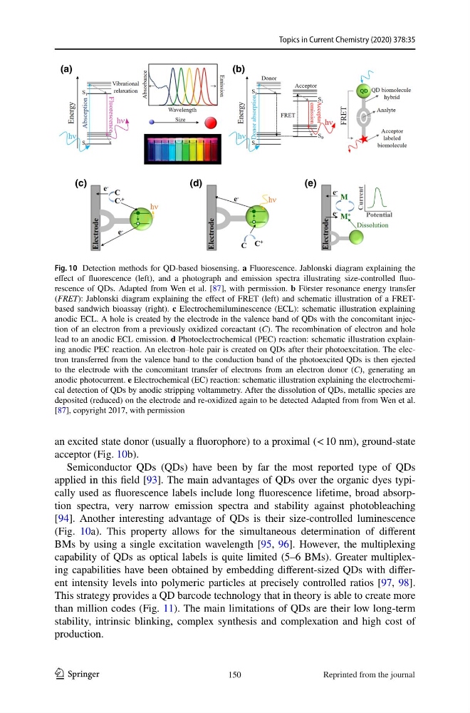
an excited state donor (usually a fluorophore) to a proximal (< 10 nm), ground-state
acceptor (Fig. 10b).
Semiconductor QDs (QDs) have been by far the most reported type of QDs
applied in this field [93]. The main advantages of QDs over the organic dyes typically used as fluorescence labels include long fluorescence lifetime, broad absorption spectra, very narrow emission spectra and stability against photobleaching
[94]. Another interesting advantage of QDs is their size-controlled luminescence
(Fig. 10a). This property allows for the simultaneous determination of different
BMs by using a single excitation wavelength [95, 96]. However, the multiplexing
capability of QDs as optical labels is quite limited (5–6 BMs). Greater multiplexing capabilities have been obtained by embedding different-sized QDs with different intensity levels into polymeric particles at precisely controlled ratios [97, 98].
This strategy provides a QD barcode technology that in theory is able to create more
than million codes (Fig. 11). The main limitations of QDs are their low long-term
stability, intrinsic blinking, complex synthesis and complexation and high cost of
production.
Fig. 10 Detection methods for QD-based biosensing. a Fluorescence. Jablonski diagram explaining the
effect of fluorescence (left), and a photograph and emission spectra illustrating size-controlled fluorescence of QDs. Adapted from Wen et al. [87], with permission. b Förster resonance energy transfer
(FRET): Jablonski diagram explaining the effect of FRET (left) and schematic illustration of a FRETbased sandwich bioassay (right). c Electrochemiluminescence (ECL): schematic illustration explaining
anodic ECL. A hole is created by the electrode in the valence band of QDs with the concomitant injection of an electron from a previously oxidized coreactant (C). The recombination of electron and hole
lead to an anodic ECL emission. d Photoelectrochemical (PEC) reaction: schematic illustration explaining anodic PEC reaction. An electron–hole pair is created on QDs after their photoexcitation. The electron transferred from the valence band to the conduction band of the photoexcited QDs is then ejected
to the electrode with the concomitant transfer of electrons from an electron donor (C), generating an
anodic photocurrent. e Electrochemical (EC) reaction: schematic illustration explaining the electrochemical detection of QDs by anodic stripping voltammetry. After the dissolution of QDs, metallic species are
deposited (reduced) on the electrode and re-oxidized again to be detected Adapted from from Wen et al.
[87], copyright 2017, with permission
150
Reprinted from the journal
1 3
an excited state donor (usually a fluorophore) to a proximal (< 10 nm), ground-state
acceptor (Fig. 10b).
Semiconductor QDs (QDs) have been by far the most reported type of QDs
applied in this field [93]. The main advantages of QDs over the organic dyes typically used as fluorescence labels include long fluorescence lifetime, broad absorption spectra, very narrow emission spectra and stability against photobleaching
[94]. Another interesting advantage of QDs is their size-controlled luminescence
(Fig. 10a). This property allows for the simultaneous determination of different
BMs by using a single excitation wavelength [95, 96]. However, the multiplexing
capability of QDs as optical labels is quite limited (5–6 BMs). Greater multiplexing capabilities have been obtained by embedding different-sized QDs with different intensity levels into polymeric particles at precisely controlled ratios [97, 98].
This strategy provides a QD barcode technology that in theory is able to create more
than million codes (Fig. 11). The main limitations of QDs are their low long-term
stability, intrinsic blinking, complex synthesis and complexation and high cost of
production.
Fig. 10 Detection methods for QD-based biosensing. a Fluorescence. Jablonski diagram explaining the
effect of fluorescence (left), and a photograph and emission spectra illustrating size-controlled fluorescence of QDs. Adapted from Wen et al. [87], with permission. b Förster resonance energy transfer
(FRET): Jablonski diagram explaining the effect of FRET (left) and schematic illustration of a FRETbased sandwich bioassay (right). c Electrochemiluminescence (ECL): schematic illustration explaining
anodic ECL. A hole is created by the electrode in the valence band of QDs with the concomitant injection of an electron from a previously oxidized coreactant (C). The recombination of electron and hole
lead to an anodic ECL emission. d Photoelectrochemical (PEC) reaction: schematic illustration explaining anodic PEC reaction. An electron–hole pair is created on QDs after their photoexcitation. The electron transferred from the valence band to the conduction band of the photoexcited QDs is then ejected
to the electrode with the concomitant transfer of electrons from an electron donor (C), generating an
anodic photocurrent. e Electrochemical (EC) reaction: schematic illustration explaining the electrochemical detection of QDs by anodic stripping voltammetry. After the dissolution of QDs, metallic species are
deposited (reduced) on the electrode and re-oxidized again to be detected Adapted from from Wen et al.
[87], copyright 2017, with permission
150
Reprinted from the journal