

14.1 Neural Networks as Logic Systems
581
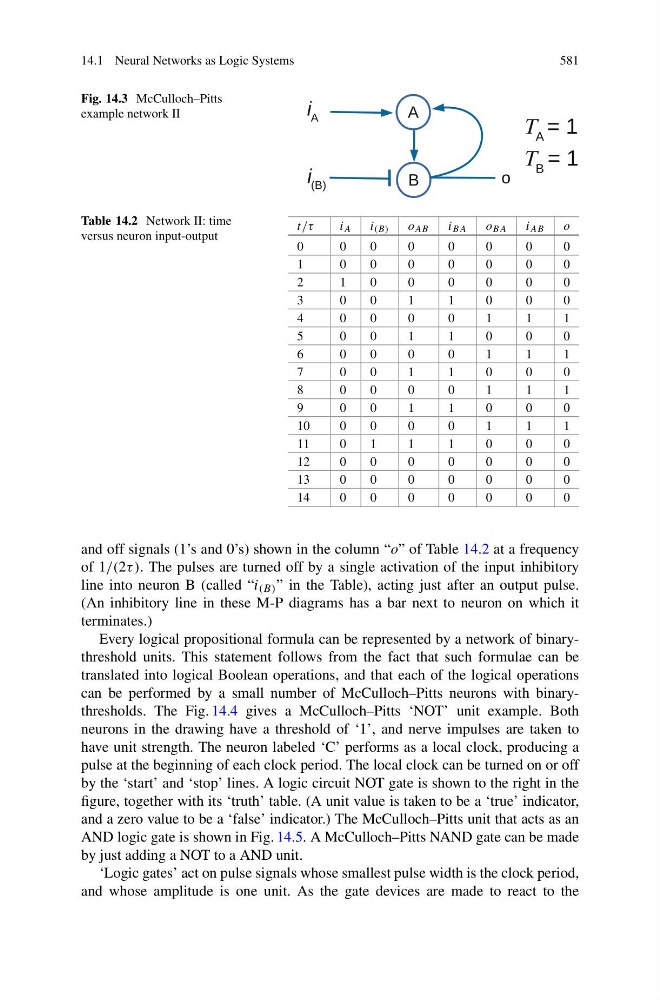
Fig. 14.3 McCulloch–Pitts
example network II
Table 14.2 Network II: time
versus neuron input-output
t/τ
i A
i (B)
o AB
i BA
o BA
i AB
o
0
0
0
0
0
0
0
0
1
0
0
0
0
0
0
0
2
1
0
0
0
0
0
0
3
0
0
1
1
0
0
0
4
0
0
0
0
1
1
1
5
0
0
1
1
0
0
0
6
0
0
0
0
1
1
1
7
0
0
1
1
0
0
0
8
0
0
0
0
1
1
1
9
0
0
1
1
0
0
0
1 0
0
0
0
0
1
1
1
1 1
0
1
1
1
0
0
0
1 2
0
0
0
0
0
0
0
1 3
0
0
0
0
0
0
0
1 4
0
0
0
0
0
0
0
and off signals (1’s and 0’s) shown in the column “o” of Table 14.2 at a frequency
of 1/(2τ ). The pulses are turned off by a single activation of the input inhibitory
line into neuron B (called “i (B) ” in the Table), acting just after an output pulse.
(An inhibitory line in these M-P diagrams has a bar next to neuron on which it
terminates.)
Every logical propositional formula can be represented by a network of binarythreshold units. This statement follows from the fact that such formulae can be
translated into logical Boolean operations, and that each of the logical operations
can be performed by a small number of McCulloch–Pitts neurons with binarythresholds. The Fig. 14.4 gives a McCulloch–Pitts ‘NOT’ unit example. Both
neurons in the drawing have a threshold of ‘1’, and nerve impulses are taken to
have unit strength. The neuron labeled ‘C’ performs as a local clock, producing a
pulse at the beginning of each clock period. The local clock can be turned on or off
by the ‘start’ and ‘stop’ lines. A logic circuit NOT gate is shown to the right in the
figure, together with its ‘truth’ table. (A unit value is taken to be a ‘true’ indicator,
and a zero value to be a ‘false’ indicator.) The McCulloch–Pitts unit that acts as an
AND logic gate is shown in Fig. 14.5. A McCulloch–Pitts NAND gate can be made
by just adding a NOT to a AND unit.
‘Logic gates’ act on pulse signals whose smallest pulse width is the clock period,
and whose amplitude is one unit. As the gate devices are made to react to the