

1 3
Topics in Current Chemistry (2019) 377:2
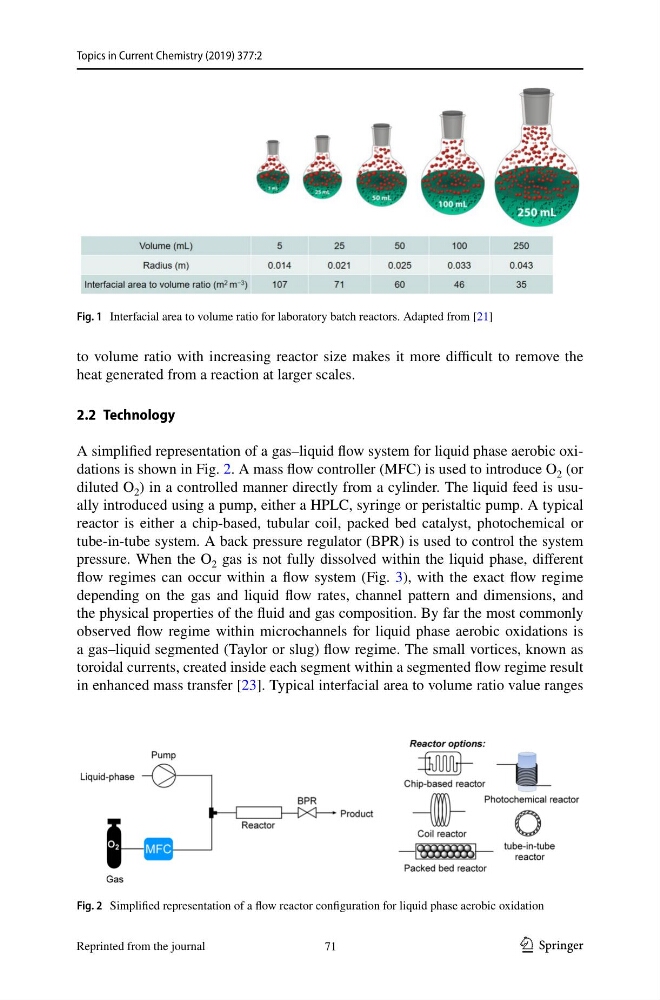
to volume ratio with increasing reactor size makes it more difficult to remove the
heat generated from a reaction at larger scales.
2.2 Technology
A simplified representation of a gas–liquid flow system for liquid phase aerobic oxi‑
dations is shown in Fig. 2. A mass flow controller (MFC) is used to introduce O 2 (or
diluted O 2 ) in a controlled manner directly from a cylinder. The liquid feed is usu‑
ally introduced using a pump, either a HPLC, syringe or peristaltic pump. A typical
reactor is either a chip‑based, tubular coil, packed bed catalyst, photochemical or
tube‑in‑tube system. A back pressure regulator (BPR) is used to control the system
pressure. When the O 2 gas is not fully dissolved within the liquid phase, different
flow regimes can occur within a flow system (Fig. 3), with the exact flow regime
depending on the gas and liquid flow rates, channel pattern and dimensions, and
the physical properties of the fluid and gas composition. By far the most commonly
observed flow regime within microchannels for liquid phase aerobic oxidations is
a gas–liquid segmented (Taylor or slug) flow regime. The small vortices, known as
toroidal currents, created inside each segment within a segmented flow regime result
in enhanced mass transfer [23]. Typical interfacial area to volume ratio value ranges
Fig. 1 Interfacial area to volume ratio for laboratory batch reactors. Adapted from [21]
Fig. 2 Simplified representation of a flow reactor configuration for liquid phase aerobic oxidation
71
Reprinted from the journal
Topics in Current Chemistry (2019) 377:2
to volume ratio with increasing reactor size makes it more difficult to remove the
heat generated from a reaction at larger scales.
2.2 Technology
A simplified representation of a gas–liquid flow system for liquid phase aerobic oxi‑
dations is shown in Fig. 2. A mass flow controller (MFC) is used to introduce O 2 (or
diluted O 2 ) in a controlled manner directly from a cylinder. The liquid feed is usu‑
ally introduced using a pump, either a HPLC, syringe or peristaltic pump. A typical
reactor is either a chip‑based, tubular coil, packed bed catalyst, photochemical or
tube‑in‑tube system. A back pressure regulator (BPR) is used to control the system
pressure. When the O 2 gas is not fully dissolved within the liquid phase, different
flow regimes can occur within a flow system (Fig. 3), with the exact flow regime
depending on the gas and liquid flow rates, channel pattern and dimensions, and
the physical properties of the fluid and gas composition. By far the most commonly
observed flow regime within microchannels for liquid phase aerobic oxidations is
a gas–liquid segmented (Taylor or slug) flow regime. The small vortices, known as
toroidal currents, created inside each segment within a segmented flow regime result
in enhanced mass transfer [23]. Typical interfacial area to volume ratio value ranges
Fig. 1 Interfacial area to volume ratio for laboratory batch reactors. Adapted from [21]
Fig. 2 Simplified representation of a flow reactor configuration for liquid phase aerobic oxidation
71
Reprinted from the journal