

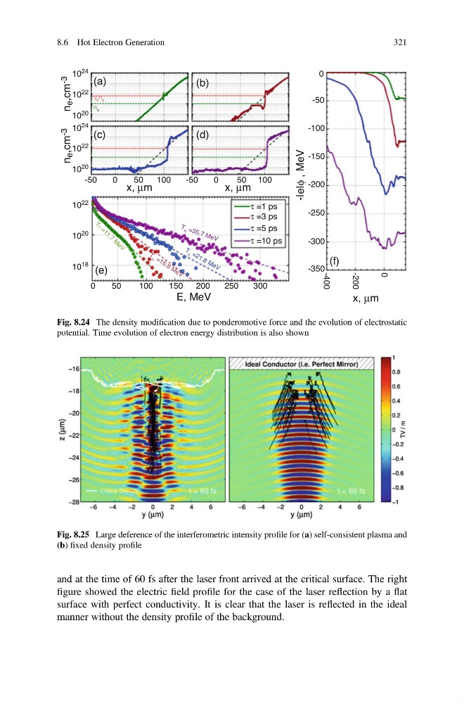
and at the time of 60 fs after the laser front arrived at the critical surface. The right
figure showed the electric field profile for the case of the laser reflection by a flat
surface with perfect conductivity. It is clear that the laser is reflected in the ideal
manner without the density profile of the background.
10
24
10 22
10
22
10
20
(a)
(c)
(e)
(f)
n
e ,cm -3
n
e ,cm -3
(d)
(b)
10
24
10
22
10 20
10
20
10
18
-50
-50
-100
-150
-200
-250
-300
-350
-400
-200
0
50
x, μm
γ 0 n e
E, MeV
x, μm
x, μm
100
0
0
50
100
150
T
n = 3 5 .7 M e V
T
n = 2 1 .8 M e V
T
n = 1 6 .8 M e V
T n = 1 1 . 7 M e V
200
250
300
0
-50
50 100
τ =1 ps
τ =3 ps
τ =5 ps
τ =10 ps
-|e|φ , MeV
0
n e
Fig. 8.24 The density modification due to ponderomotive force and the evolution of electrostatic
potential. Time evolution of electron energy distribution is also shown
Fig. 8.25 Large deference of the interferometric intensity profile for (a) self-consistent plasma and
(b) fixed density profile
8.6 Hot Electron Generation
321
figure showed the electric field profile for the case of the laser reflection by a flat
surface with perfect conductivity. It is clear that the laser is reflected in the ideal
manner without the density profile of the background.
10
24
10 22
10
22
10
20
(a)
(c)
(e)
(f)
n
e ,cm -3
n
e ,cm -3
(d)
(b)
10
24
10
22
10 20
10
20
10
18
-50
-50
-100
-150
-200
-250
-300
-350
-400
-200
0
50
x, μm
γ 0 n e
E, MeV
x, μm
x, μm
100
0
0
50
100
150
T
n = 3 5 .7 M e V
T
n = 2 1 .8 M e V
T
n = 1 6 .8 M e V
T n = 1 1 . 7 M e V
200
250
300
0
-50
50 100
τ =1 ps
τ =3 ps
τ =5 ps
τ =10 ps
-|e|φ , MeV
0
n e
Fig. 8.24 The density modification due to ponderomotive force and the evolution of electrostatic
potential. Time evolution of electron energy distribution is also shown
Fig. 8.25 Large deference of the interferometric intensity profile for (a) self-consistent plasma and
(b) fixed density profile
8.6 Hot Electron Generation
321